_____________________________________________________________________ Special Amplifiers
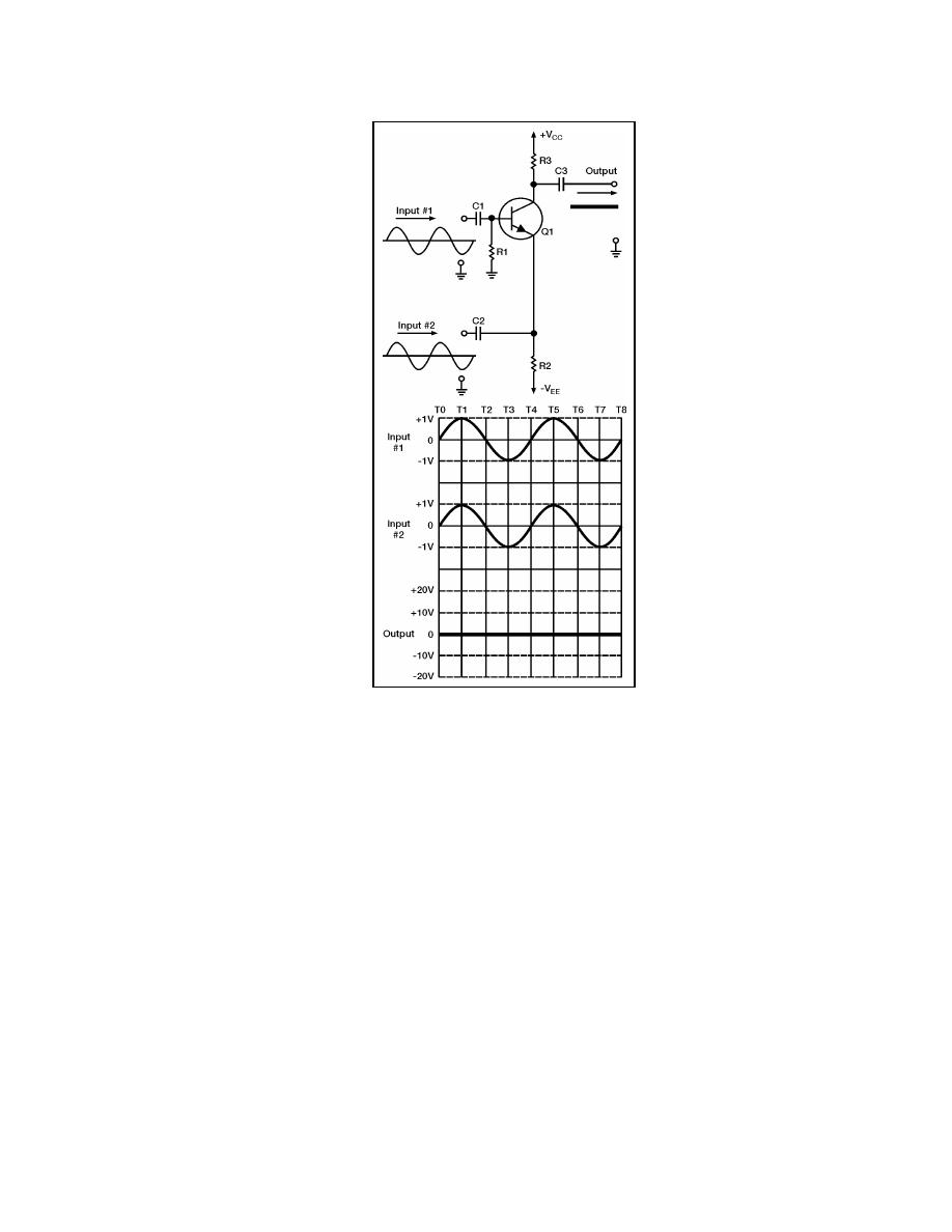
Figure 7-4. Input Signals in Phase
7-24. If you compute the bias at any time period (T0 through T8), you will see that the
output of the circuit remains at a constant zero. For example:
Bias = (input signal #1) - (input signal #2)
T1 Bias = (+V) - (+1 V) = 0 V and so forth.
7-25. From the above example, you can see that when the input signals are equal in
amplitude and in phase, there is no output from the difference amplifier because there is no
difference between the two inputs. You also know that when the input signals are equal in
amplitude but 180 degrees out of phase, the output looks just like the input except for
amplitude and a 180-degree phase reversal with respect to input signal number 1. If the
input signals are equal in amplitude but different in phase by something other than 180
degrees, then that would mean the following:
Sometimes one signal would be going negative while the other would be going
positive.
Sometimes both signals would be going positive.
Sometimes both signals would be going negative.
23 June 2005
TC 9-62
7-7


 Previous Page
