_____________________________________________________________________ Special Amplifiers
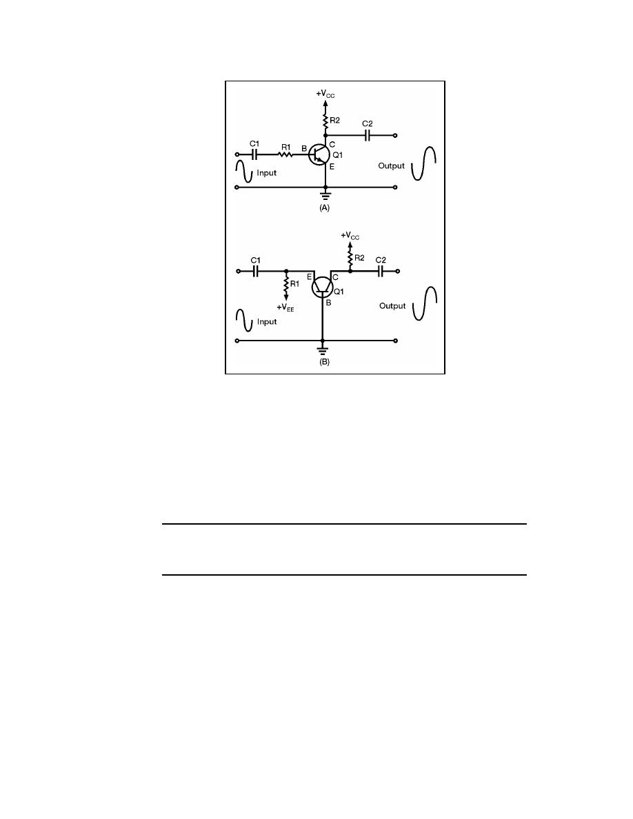
Figure 7-1. Common Emitter and Common Base Amplifiers
7-11. Figure 7-1, view (A) shows a CE amplifier. The output signal is an amplified
version of the input signal and is 180 degrees out of phase with the input signal. View (B)
is a CB amplifier. In this circuit, the output signal is an amplified version of the input
signal and is in phase with the input signal. In both of these circuits, the output signal is
controlled by the base-to-emitter bias. As this bias changes (because of the input signal) the
current through the transistor changes. This causes the output signal developed across the
collector load (R2) to change. None of this information is new; this is just a review of what
you have already been shown regarding transistor amplifiers.
NOTE: Bias arrangements for the following explanations will be termed base-
to-emitter. In other publications you will see the term emitter-to-base used to
describe the same bias arrangement.
THE TWO-INPUT, SINGLE-OUTPUT, DIFFERENCE AMPLIFIER
7-12. If you combine the CB and CE configurations into a single transistor amplifier,
you will have a circuit like the one shown in Figure 7-2. This circuit is the two-input,
single-output, difference amplifier.
7-13. The transistor shown in Figure 7-2 has two inputs (the emitter and the base) and
one output (the collector). Remember that the current through the transistor, and therefore
the output signal, is controlled by the base-to-emitter bias. In the circuit, the combination
of the two input signals controls the output signal. In fact, the difference between the input
signals determines the base-to-emitter bias.
23 June 2005
TC 9-62
7-3


 Previous Page
