_____________________________________________________________________ Special Amplifiers
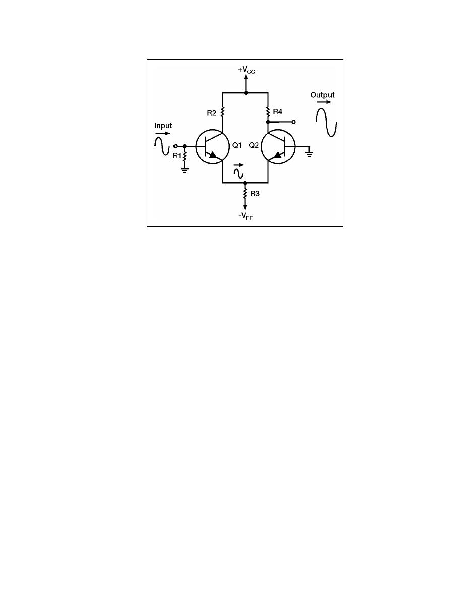
Figure 7-7. Single-input, Single-output Differential Amplifier
7-34. When the input signal developed by R1 goes negative, the current through Q1
decreases. This decreased current causes a negative-going signal at the top of R3. This
signal is felt on the emitter of Q2. When the emitter of Q2 goes negative, the current
through Q2 increases. This increased current causes more of a voltage drop across R4.
Therefore, the voltage at the bottom of R4 decreases and a negative-going signal is felt at
the output.
7-35. This single-input, single-output, differential amplifier is very similar to a single-
transistor amplifier as far as input and output signals are concerned. This use of a
differential amplifier does provide amplification of AC or DC signals but does not take full
advantage of the characteristics of a differential amplifier.
SINGLE-INPUT, DIFFERENTIAL-OUTPUT, DIFFERENTIAL AMPLIFIER
7-36. In chapter 5 you were shown several phase splitters. Remember that a phase
splitter provides two outputs from a single input. These two outputs are 180 degrees out of
phase with each other. The single-input, differential-output, differential amplifier will do
the same thing.
7-37. Figure 7-8 shows a differential amplifier with one input (the base of Q1) and two
outputs (the collectors of Q1 and Q2). One output is in phase with the input signal and the
other output is 180 degrees out of phase with the input signal. The outputs are differential
outputs.
7-38. The input signal is developed by R1. As the current through Q1 varies with the
input signal, the voltage at the top of R3 will vary with the input signal. This causes a
signal to be felt on the emitter of Q2. This signal on the emitter of Q2 causes the current to
vary (180 degrees out of phase with the input signal) through Q2. The variations of current
in Q1 and Q2 are developed by R2 and R4, respectively, as output number one and output
number two.
23 June 2005
TC 9-62
7-11


 Previous Page
