TC 9-62
6-55. In many electronic devices (such as radio or television receivers or radar systems),
a particular frequency must be selected from a band of frequencies. Do this by using a
separate RF amplifier for each frequency and then turning on the appropriate RF amplifier.
It would be more efficient if a single RF amplifier could be "tuned" to the particular
frequency as that frequency is needed. This is what happens when you select a channel on
your television set or tune to a station on your radio. To accomplish this "tuning," you need
only change the value of inductance or capacitance in the parallel LC circuits (tuned
circuits).
6-56. In most cases, the capacitance is changed by the use of variable capacitors. The
capacitors in the input and output portions of all the RF amplifier stages are ganged
together in order that they can all be changed at one time with a single device (such as the
tuning dial on a radio). This technique will be shown later on in a schematic.
RF AMPLIFIER COUPLING
6-57. Figure 6-13 and the other circuits you have been shown use capacitors to couple
the signal into and out of the circuit (see C1 and C4 in Figure 6-13). Chapter 5 covered
other methods of coupling signals from one stage to another. Transformer coupling is the
most common method used to couple RF amplifiers. Transformer coupling has many
advantages over RC coupling for RF amplifiers. For example, transformer coupling uses
fewer components than capacitive coupling. It can also provide a means of increasing the
gain of the stage by using a step-up transformer for voltage gain. If a current gain is
required, a step-down transformer can be used.
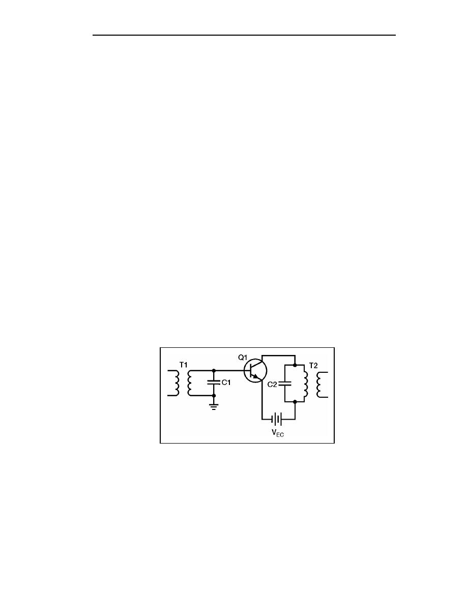
6-58. Remember that the primary and secondary windings of a transformer are inductors.
With these factors in mind, an RF amplifier could be constructed like the one shown in
Figure 6-14. In this circuit, the secondary of T1 and capacitor C1 form a tuned circuit,
which is the input-signal-developing impedance. The primary of T2 and capacitor C2 are a
tuned circuit, which acts as the output impedance of Q1. T1 and T2 must be RF
transformers in order to operate at RF frequencies.
Figure 6-14. Transformer-coupled RF Amplifier
6-59. The input signal applied to the primary of T1 could come from the previous stage
or from some input device, such as a receiving antenna. In either case, the input device
would have a capacitor connected across a coil to form a tuned circuit. In the same way,
the secondary of T2 represents the output of this circuit. A capacitor connected across the
secondary of T2 would form a parallel LC network. This network could act as the input-
signal-developing impedance for the next stage, or the network could represent some type
of output device, such as a transmitting antenna.
6-16
TC 9-62
23 June 2005


 Previous Page
