____________________________________________________ Video and Radio Frequency Amplifiers
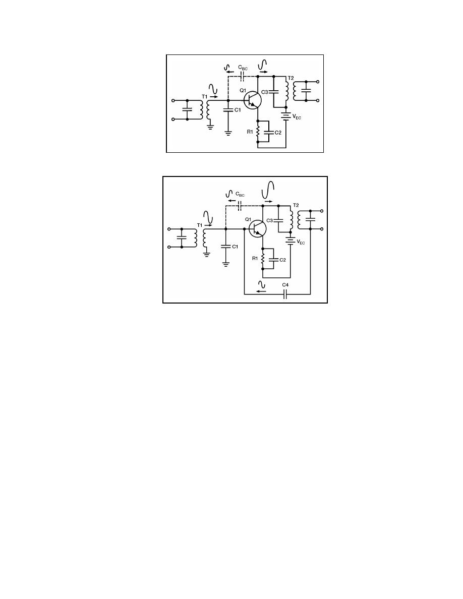
Figure 6-16. Interelectrode Capacitance in an RF Amplifier
Figure 6-17. Neutralized RF Amplifier
6-72. In Figure 6-17, a feedback capacitor (C4) has been added to neutralize the
amplifier. This solves the problem of unwanted degenerative feedback. Except for
capacitor C4, this circuit is identical to the circuit shown in Figure 6-16. When CBC causes
regenerative feedback, C4 will still neutralize the amplifier. This is true because C4 always
provides a feedback signal that is 180 degrees out of phase with the feedback signal caused
by CBC.
TYPICAL RF AMPLIFIER CIRCUITS
6-73. You will see many different RF amplifiers in many different pieces of equipment.
The particular circuit configuration used for an RF amplifier will depend upon how that
amplifier is used.
6-74. Figure 6-18 is the schematic diagram of a typical RF amplifier that is used in an
AM radio receiver. In Figure 6-18, the input circuit is the antenna of the radio (L1―a coil)
that forms part of an LC circuit that is tuned to the desired station by variable capacitor C1.
L1 is wound on the same core as L2, which couples the input signal through C2 to the
transistor (Q1). R1 is used to provide proper bias to Q1 from the base power supply (VBB).
R2 provides proper bias to the emitter of Q1 and C3 is used to bypass R2. The primary of
T1 and capacitor C4 form a parallel LC circuit, which acts as the load for Q1. This LC
circuit is tuned by C4, which is ganged to C1 allowing the antenna and the LC circuit to be
tuned together. The primary of T1 is center-tapped to provide proper impedance matching
with Q1.
23 June 2005
TC 9-62
6-19


 Previous Page
