____________________________________________________ Video and Radio Frequency Amplifiers
Table 6-1. Value Chart
R1
R2
RT
0
200
0.00
10
190
9.50
25
175
21.88
50
150
37.50
75
125
46.88
100
100
50.00
125
75
46.88
150
50
37.50
175
25
21.88
190
10
9.50
200
0
0.00
6-52. There are components that will vary their impedance (reactance) like the ganged
resistors. As you know, the reactance of an inductor and a capacitor vary as frequency
changes. As frequency increases, inductive reactance increases and capacitive reactance
decreases.
6-53. At some frequency, inductive and capacitive reactance will be equal. That
frequency will depend upon the value of the inductor and capacitor. If the inductor and
capacitor are connected as a parallel LC circuit, you will have the ideal frequency-
determining network for an RF amplifier.
6-54. The parallel LC circuit used as a frequency-determining network is called a tuned
circuit. This circuit is "tuned" to give the proper response at the desired frequency by
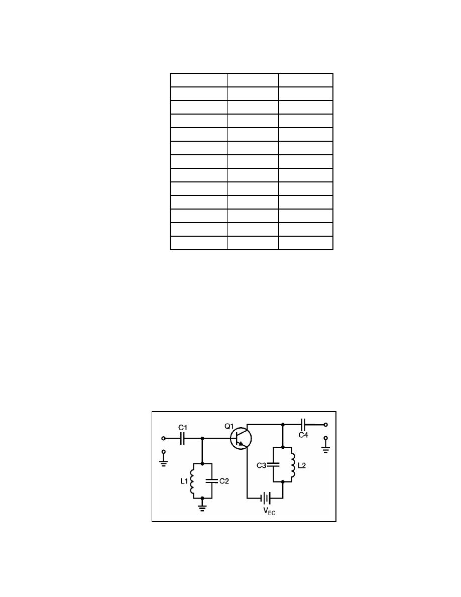
selecting the proper values of inductance and capacitance. Figure 6-13 shows a circuit
using this principle. The figure shows an RF amplifier with parallel LC circuits used as
frequency-determining networks. This RF amplifier will only be effective in amplifying
the frequency determined by the parallel LC circuits.
Figure 6-13. Simple RF Amplifier
23 June 2005
TC 9-62
6-15


 Previous Page
