TC 9-62
RADIO FREQUENCY AMPLIFIERS
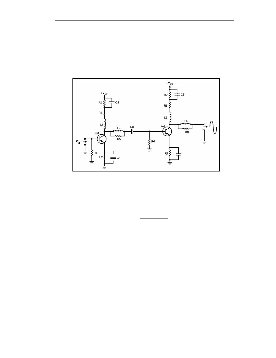
6-41. You have seen the way in which a broadband or video amplifier can be
constructed. RF amplifiers use different techniques, so they are very different than video
amplifiers. Before you study the specific techniques used in RF amplifiers, you should
review some information on the relationship between the input and output impedance of an
amplifier and the gain of the amplifier stage.
Figure 6-9. Video Amplifier Circuit
AMPLIFIER INPUT/OUTPUT IMPEDANCE AND GAIN
6-42. You should remember that the gain of a stage is calculated by using the input
signals. Use the following formula to calculate the gain of a stage:
output signal
gain =
input signal
6-43. Voltage gain is calculated using input and output voltage; current gain uses input
and output current; and power gain uses input and output power. For the purposes of our
discussion, we will only be concerned with voltage gain.
6-44. Figure 6-10 shows a simple amplifier circuit with the input and output signal
developing impedances represented by variable resistors. In this circuit, C1 and C2 are the
input and output coupling capacitors. R1 represents the impedance of the input circuit. R2
represents the input-signal-developing impedance and R3 represents the output impedance.
6-12
TC 9-62
23 June 2005


 Previous Page
