TC 9-62
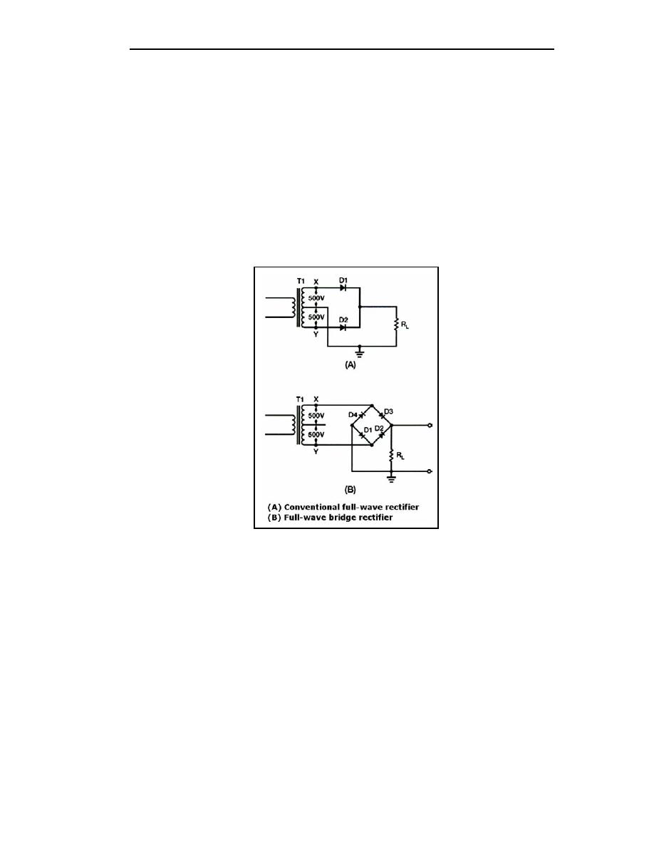
as that of the conventional full-wave circuit. This may be shown by assigning values to
some of the components (see Figure 4-9, views (A) and (B)). Assume that the same
transformer is issued in both circuits. The peak voltage developed between points X and Y
is 1,000 volts in both circuits. In the conventional full-wave circuit shown in view (A), the
peak voltage from the center tap to either X or Y is 500 volts. Since only one diode can
conduct at any instant, the maximum voltage that can be rectified at any instant is 500
volts. Therefore, the maximum voltage that appears across the load resistor is nearly (but
never exceeds) 500 volts. This is a result of the small voltage drop across the diode. In the
bridge rectifier shown in view (B), the maximum voltage that can be rectified is the full
secondary voltage, which is 1,000 volts. Therefore, the peak output voltage across the load
resistor is nearly 1,000 volts. With both circuits using the same transformer, the bridge
rectifier circuit produces a higher output voltage than the conventional full-wave rectifier
circuit.
Figure 4-9. Comparison of a Conventional and Bridge Full-wave Rectifier
FILTERS
4-27. While the output of a rectifier is a pulsating DC, most electronic circuits require a
substantially pure DC for proper operation. Single or multisection filter circuits, placed
between the output of the rectifier and the load, provide this type of output. The following
are the four basic types of filter circuits:
Simple capacitor filter.
LC choke-input filter.
LC capacitor-input filter (pi-type).
RC capacitor-input filter (pi-type).
4-28. Filtering is accomplished by the use of capacitors, inductors, and/or resistors in
different combinations. Inductors are used as series impedances to oppose the flow of
alternating (pulsating DC) current. Capacitors are used as shunt elements to bypass the
4-10
TC 9-62
23 June 2005


 Previous Page
