_______________________________________________________________________ Special Devices
3-31. In general, varactors are used to replace the old style variable capacitor tuning.
They are used in tuning circuits of more sophisticated communication equipment and in
other circuits where variable capacitance is required. One advantage of the varactor is that
it allows a DC voltage to be used to tune a circuit for simple remote control or automatic
tuning functions. One such application of the varactor is as a variable tuning capacitor in a
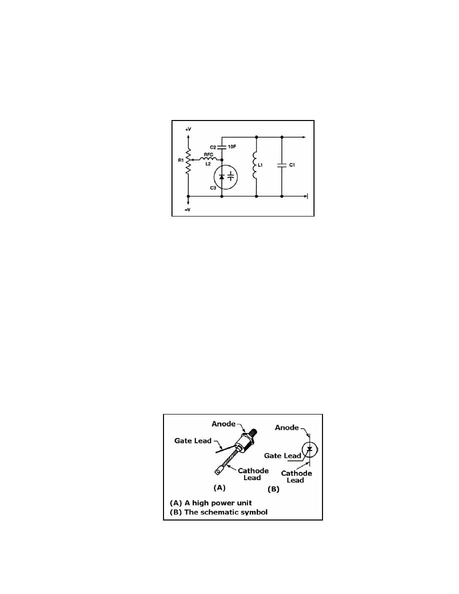
receiver or transmitter tank circuit (see Figure 3-16).
Figure 3-16. Varactor Tuned Resonant Circuit
3-32. Figure 3-16 also shows a DC voltage felt at the wiper of potentiometer R1 that can
be adjusted between +V and -V. The DC voltage, passed through the low resistance of
radio frequency choke L2, acts to reverse bias varactor diode C3. The capacitance of C3 is
in series with C2, and the equivalent capacitance of C2 and C3 is in parallel with tank
circuit L1-C1. Therefore, any variation in the DC voltage at R1 will vary both the
capacitance of C3 and the resonant frequency of the tank circuit. The RF choke provides
high inductive reactance at the tank frequency to prevent tank loading by R1. C2 acts to
block DC from the tank as well as to fix the tuning range of C3.
3-33. An ohmmeter can be used to check a varactor diode in a circuit. A high reverse-
bias resistance and a low forward-bias resistance with a 10 to 1 ratio in reverse-bias to
forward-bias resistance is considered normal.
Silicon Controlled Rectifier
3-34. The SILICON CONTROLLED RECTIFIER is one of the families of
semiconductors that include transistors and diodes. Figure 3-17, views (A) and (B) shows a
drawing of an SCR and its schematic representation. Not all SCRs use the casing shown.
However, this is typical of most of the high-power units.
Figure 3-17. Silicon Controlled Rectifier Schematic
23 June 2005
TC 9-62
3-11


 Previous Page
