TC 9-62
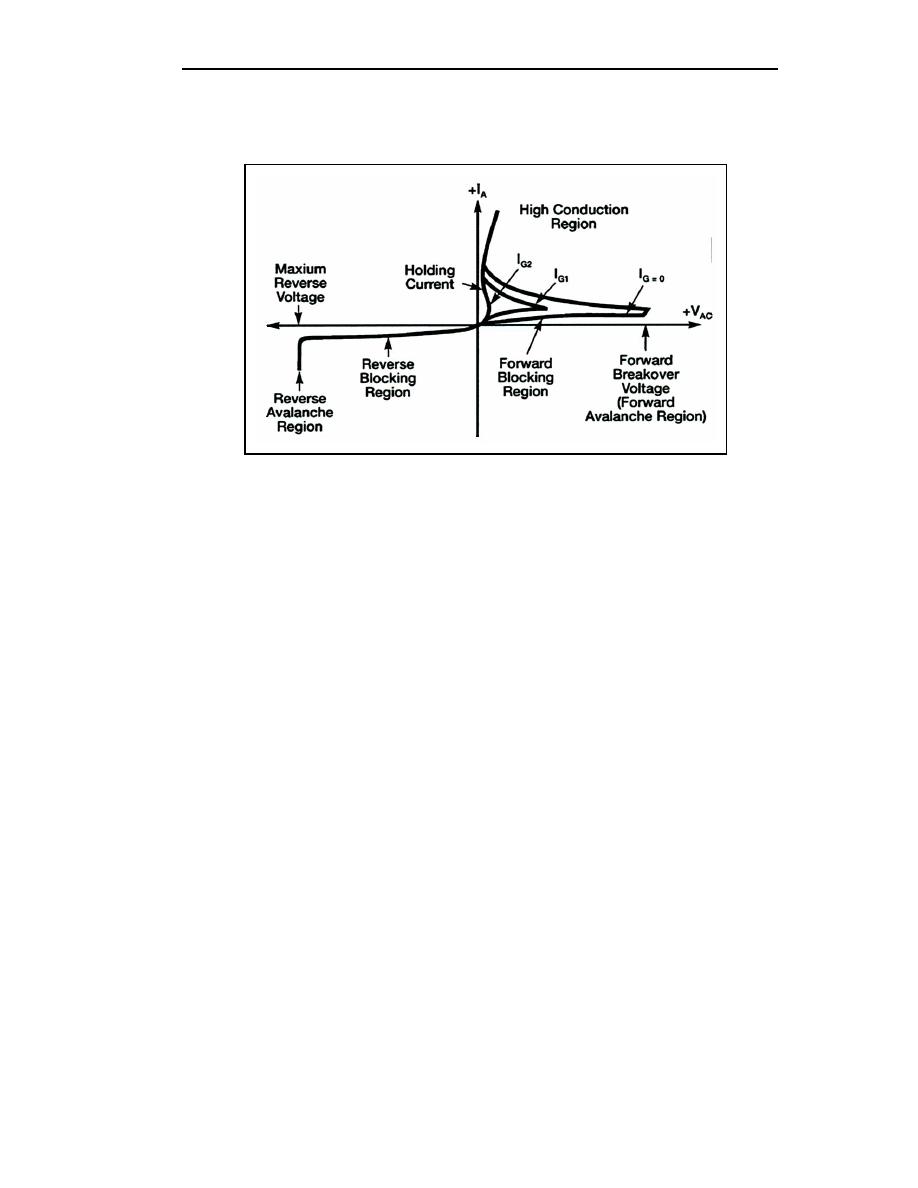
breakdown, the voltage across the device is so low that the current through it from cathode
to anode is essentially determined by the load it is feeding.
Figure 3-20. SCR Characteristic Curve With Various Gate Signals
3-44. The important thing to remember is that a small current from gate to cathode can
fire or trigger the SCR, changing it from practically an open circuit to a short circuit. The
only way to change it back again (to commutate it) is to reduce the load current to a value
less than the minimum forward-bias current. Gate current is required only until the anode
current has completely built up to a point sufficient to sustain conduction (about five
microseconds in resistive-load circuits). After conduction from cathode to anode begins,
removing the gate current has no effect.
3-45. The basic operation of the SCR can be compared to that of the thyratron. The
thyratron is an electron tube, normally gas filled, that uses a filament or a heater. The SCR
and the thyratron function in almost the same manner. Figure 3-21 shows the schematic of
each with the corresponding elements labeled. In both types of devices, control by the
input signal is lost after they are triggered. The control grid (thyratron) and the gate (SCR)
have no further affect on the magnitude of the load current after conduction begins. The
load current can be interrupted by one or more of the following three methods:
The load circuit must be opened by a switch.
The plate (anode) voltage must be reduced below the ionizing potential of the
gas (thyratron).
The forward-bias current must be reduced below a minimum value required to
sustain conduction (SCR).
The input resistance of the SCR is relatively low (approximately 100 ohms) and requires a
current for triggering. The input resistance of the thyratron is exceptionally high and
requires a voltage input to the grid for triggering action.
3-14
TC 9-62
23 June 2005


 Previous Page
