TC 9-62
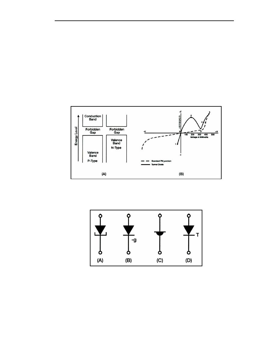
3-23. Figure 3-9, view (A), is the energy diagram of a tunnel diode in which the forward
bias has been increased even further. The energy bands no longer overlap and the diode
operates in the same manner as a normal PN junction, as shown by the portion of the curve
in view (B) from point 3 to point 4.
3-24. The negative resistance region is the most important and most widely used
characteristic of the tunnel diode. A tunnel diode biased to operate in the negative
resistance region can be used as either an oscillator or an amplifier in a wide range of
frequencies and applications. Very high frequency applications using the tunnel diode are
possible because the tunneling action occurs so rapidly that there is no transit time effect
and therefore no signal distortion. Tunnel diodes are also used extensively in high-speed
switching circuits because of the speed of the tunneling action.
Figure 3-9. Tunnel Diode Energy Diagram With 600 Millivolts Bias
3-25. Several schematic symbols are used to indicate tunnel diodes. These symbols are
shown in Figure 3-10, views (A) through (D).
Figure 3-10. Tunnel Diode Schematic Symbols
Varactor
3-26. The VARACTOR, or varicap, as the schematic drawing in Figure 3-11 suggests, is
a diode that behaves like a variable capacitor, with the PN junction functioning like the
dielectric and plates of a common capacitor. Understanding how the varactor operates is an
important prerequisite to understanding field-effect transistors, which will be covered later
in this chapter.
3-8
TC 9-62
23 June 2005


 Previous Page
