Example Problem
Design the form for the roof of a concrete water tank to be 6 inches thick, 20 feet wide, and 30 feet long. The slab
will be constructed 8 feet above the floor (to the bottom of the slab). Available materials are 3/4-inch plywood
and 4- by 4-inch S4S (surfaced on four sides) lumber. Mechanical buggies will be used to place concrete.
Step 1. Specify the materials for construction. Sheathing 3/4-inch plywood (strong way); joists, 4- by 4-inch
(S4S) shores, 4- by 4-inch (S4S); stringers, and 4- by 4-inch (S4S) lumber.
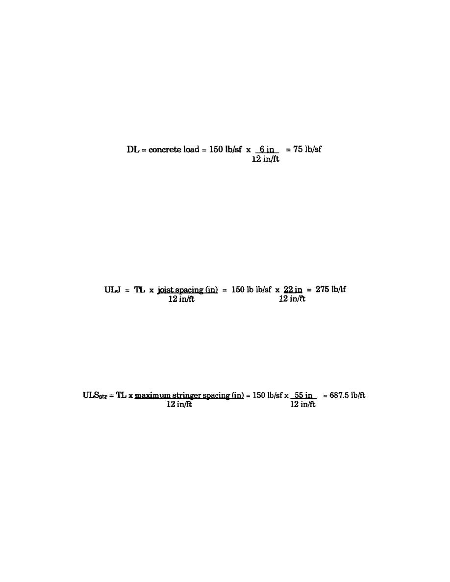
Step 2. Determine the maximum total load.
LL- = personnel and equipment = 75 lb/sf
TL = DL + LL = 75 lb/sf + 75 lb/sf = 150 lb/sf
Step 3. Determine the maximum joist spacing. Use Table 3-2 on page 3-7.
3/4-inch plywood (strong way) and TL = 150 lb/sf
Joist spacing = 22 inches
Step 4. Calculate the ULJ.
Step 5. Determine the maximum stringer spacing. Use Table 3-3 on page 3-9.
Load
= 275 lb/lf
Joist material
= 4- by 4-inch
Maximum stringer spacing
= 55 inches
Step 6. Calculate the uniform load on the stringer (ULSstr).
Step 7. Determine the maximum shore spacing (use Table 3-3). Spacing is based on stringer strength. (Use
Table 3-4 on page 3-11.)
Load
= 687.5 lb/lf (round up to 700 lb/lf)
Stringer material
= 4- by 4-inch (S4S)
Maximum shore spacing
= 35 inches
Spacing based on the shore strength and end bearing of the shore on the stringer. Use Table 3-7 on page 3-21 and
Table 3-8.
Allowable load based on shore strength (see Table 3-7).
3-2
EN5466


 Previous Page
