Shores. Support the stringers against deflection. Perform the same functions as tie in a wall form and
also support the concrete at the desired elevation above ground. Use lumber at least as large as the
stringer but never smaller than 4 by 4 inches in dimension.
Lateral bracing. May be required between adjacent shores to keep shores from bending under load. Use
1- by 6-inch or larger material for bracing material. Cross or "X" bracing of some type will always be
required to support the form work material.
Procedure
Step 1. Specify the materials you will be using for the construction of the overhead roof slab. It is important that
anyone using your design will know exactly which materials to use for each of the structural members.
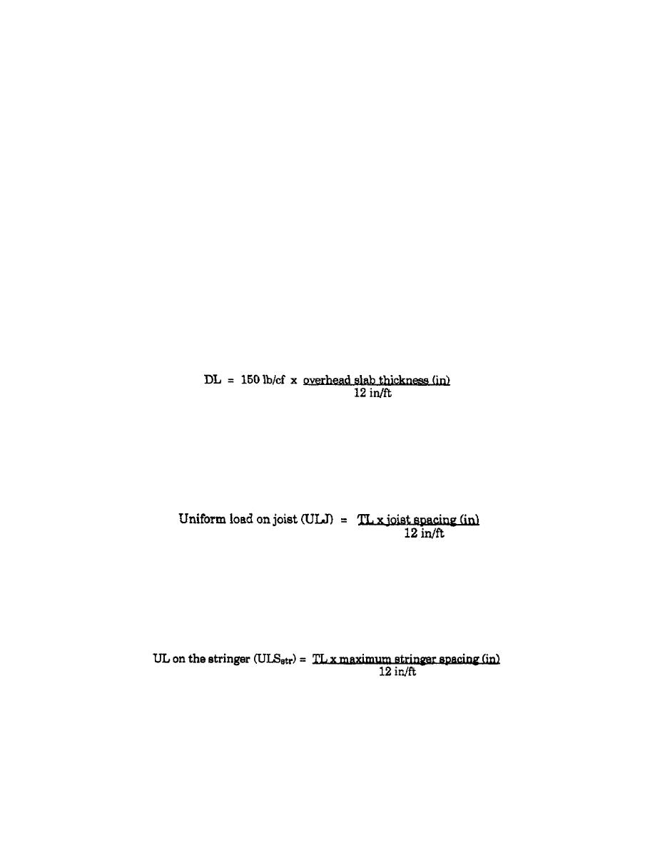
Step 2. Determine the maximum total load (TL) the formwork will have to support. The LL of materials,
personnel, and equipment is estimated to be 50 lb/sf unless the formwork will support engine-powered concrete
buggies or other power equipment. In this case, a LL of 75 lb/sf will be used. The LL is added with the dead load
of the concrete to obtain the maximum TL. The concrete dead load is obtained by estimating the unit weight of
concrete at 150 lb/cf. The formulas are--
Total load (TL) = LL + dead load (DL)
LL = 50 lb/sf, or 75 lb/sf with power equipment
Step 3. Determine the maximum joist spacing. Use Table 3-1 on page 3-6, or Table 3-2 on page 3-7, and read the
joist spacing based on the sheathing material used, which i the same as for determining the maximum stud spacing
for wall-form design. Use the maximum TL in place of the maximum concrete pressure.
Step 4. Calculate the uniform load on the joist. The same procedure is used as for determining UL on structural
members in wall-form design.
Step 5. Determine the maximum stringer spacing. Use Table 3-3 on page 3-9, and the UL on the joist calculated
in Step 4. Round this load up to the next higher load located in the left column of the table, then read right to the
column containing the lumber material used as the joist. This is the member to be supported by the stringer. The
value at this intersection is the on-center (OC) spacing of the stringer.
Step 6. Calculate the uniform load on the stringer.
Step 7.
Determine the maximum shore spacing.
Maximum shore spacing is based on the
stringer strength. Use Table 3-3, for single stringers, and use Table 3-4 on page 3-11, if stringers
are doubled and the UL on the stinger is rounded to the next higher load shown in
EN5466
3-20


 Previous Page
