Unsupported length = 8 feet - 3/4-inch - 3 1/2 inch - 3 1/2 inches = 7 feet 4 1/4 inches (round up to 8 feet)
Then, for an 8-foot 4-by 4-inch (S4S) piece of lumber, the allowable load = 5,400 lb.
Allowable load based on end-bearing stresses (see Table 8 on page 3-22). Since you do not know what
species of wood you are using you must assume the worst case. Therefore, the compression
perpendicular the grain = 250, and the allowable load for a 4- by 4-inch (S4S) = 3,100 lb.
Select the most critical load. Since the compression perpendicular to the grain is less than the allowable
load on the shore perpendicular to the grain, 3,100 pounds is the critical load.
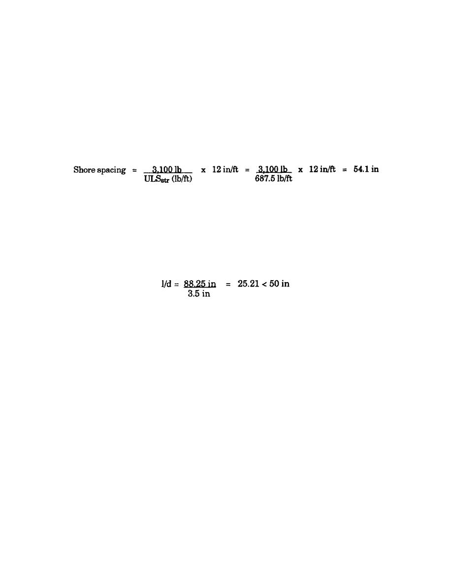
Determine shore spacing based on allowable load.
Select the most critical shore spacing. The spacing determined by stringer strength in Step 7 is less than the
spacing based on the shore strength determined in Step 7; therefore, the shore spacing to be used is 35 inches.
Step 8. Shore deflection check.
l = 8 feet - 3/4-inch - 3 1/2 inches - 3 1/2 inches = 7 foot 4 1/4 inches = 88.25 inches
d = least dimension of 4- by 4-inch (S4S) lumber = 3.5 inches
Lateral bracing is not required. Cross bracing is always required.
Step 9. Summary.
Sheathing:
1/4-inch plywood (strong way)
Joists:
4- by 4-inch (S4S) lumber spaced 22 inches OC
Stringers:
4- by 4-inch (S4S) lumber spaced 55 inches OC
Shores:
4- by 4-inch (S4S) lumber spaced 35 inches OC
Lateral braces:
Not required
Column Form Design
Procedure. Use these steps to design a wood form for a concrete column.
Step 1. Determine the materials you will use for sheathing, yokes, and battens. (Standard materials for column
forms are 2- by 4-inch and 1-inch sheathing.)
Step 2. Determine the column height.
Step 3. Determine the largest cross-sectional column dimension.
EN5466
3-24


 Previous Page
