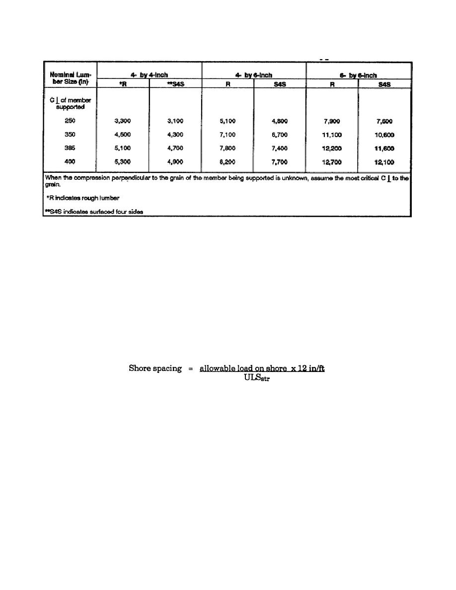
Table 3-8. Allowable load on specified shore, based on bearing stresses where
the maximum shore area is in contact with the supported member.
Allowable load based on shore strength. Select the shore material dimensions and determine the
unsupported length in feet of the shore. Use Table 3-7 on page 3-21. Read down the left column to the
unsupported length (in feet) of the shore; read right to the column of the size material used as the shore.
The allowable load for that shore is given in pounds at the intersection of the row and column.
Allowable load based on end-bearing area. Select the size of the shore material and the compression
perpendicular to the grain of the stringer. If the compression perpendicular to the grain is unknown, use
the lowest value provided on the table. Use Table 3-8. Read down the left column to the compression
perpendicular to the grain of the stringer material and then right to the column of the shore material. The
allowable load between the stringer and the shore will be in pounds.
Select the allowable load on the shore. Compare the two loads just determined and select the lower as the
allowable load on the shore. Calculate shore spacing by the following formula:
Select the most critical shore spacing. Compare the spacing of the shore based on the stringer strength and shore
load and select the smaller of the two spacings.
Step 8. Shore bracing check. Verify that the unbraced length (1) of the shore (in inches) divided by the last
dimension (d) of the shore does not exceed 50. If l/d exceeds 50, the lateral and cross bracing must be provided.
Table 3-1 on page 3-6 indicates the l/d > 50 shore lengths and can be used if the shore material is sound and
unspliced.
In any case, it is good engineering practice to provide both lateral and diagonal bracing all shore members if
material is available.
EN5466
3-22


 Previous Page
