______________________________________________________________ Solid State Power Supplies
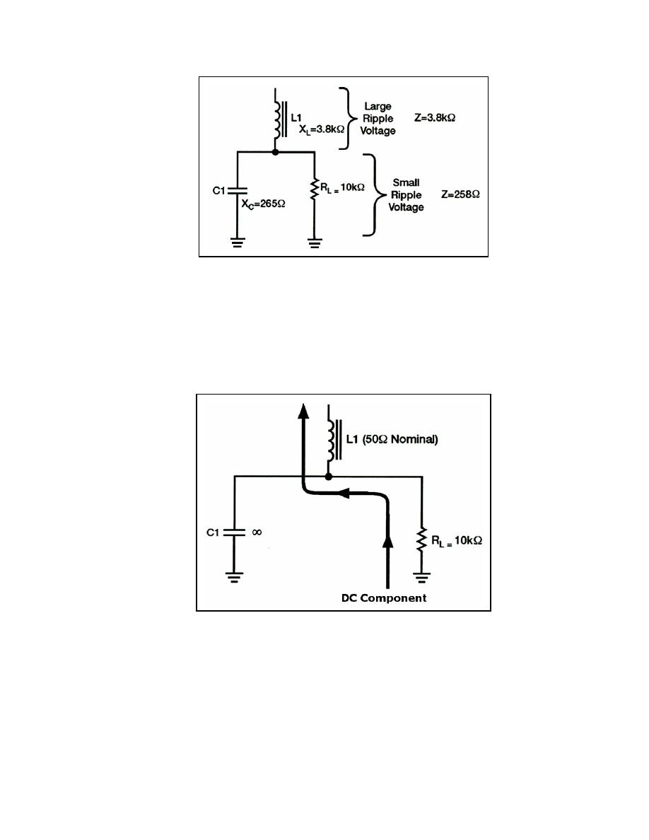
Figure 4-25. Equivalent Circuit of an LC Choke-input Filter
4-61. We will now look at the DC component of the applied voltage. Remember, a
component must flow through RL and L1. As far as the DC is concerned, the capacitor does
not exist. The coil and the load are therefore in series with each other. The DC resistance of
a filter choke is very low (50 ohms average). Consequently, most of the DC component is
developed across the load and a very small amount of the DC voltage is dropped across the
coil (see Figure 4-26).
Figure 4-26. DC Component in an LC Choke-input Filter
4-62. Notice that both the AC and DC components flow through Ll. Since it is frequency
sensitive, the coil provides a large resistance to AC and a small resistance to DC. In other
words, the coil opposes any change in current. This property makes the coil a highly
desirable filter component. Notice that the filtering action of the LC choke-input filter is
improved when the filter is used in conjunction with a full-wave rectifier (see
Figure 4-27). This is due to the decrease in the XC of the filter capacitor and the increase in
23 June 2005
TC 9-62
4-23


 Previous Page
