______________________________________________________________ Solid State Power Supplies
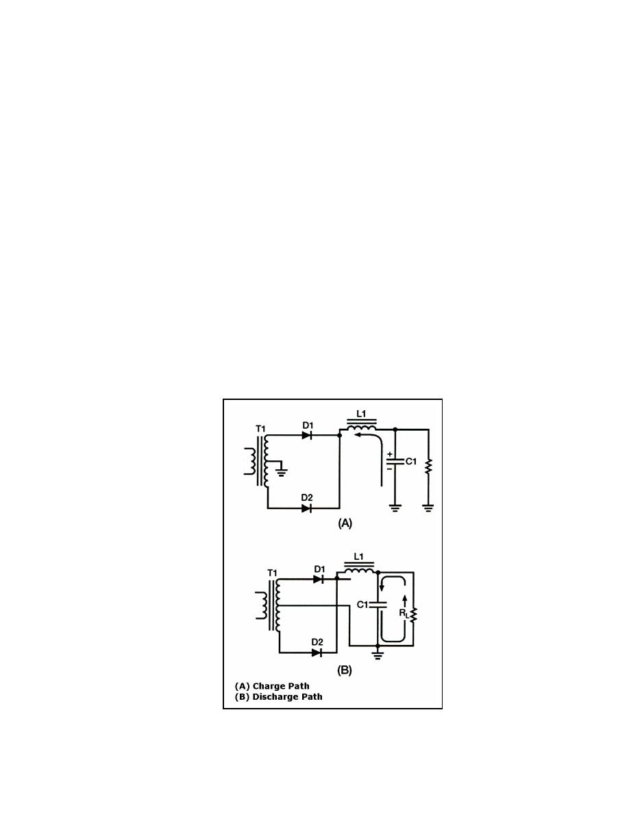
Therefore, the RC charge time constant is short compared to its discharge time. Figure
4-20, views (A) and (B) shows the comparison in RC charge and discharge paths.
Consequently, when the pulsating voltage is first applied to the LC choke-input filter, the
inductor (L1) produces a cemf that opposes the constantly increasing input voltage. The net
result is to effectively prevent the rapid charging of the filter capacitor (C1). Instead of
reaching the peak value of the input voltage, C1 only charges to the average value of the
input voltage. After the input voltage reaches its peak and decreases sufficiently, the
(B) shows that C1 will only partially discharge because of its relatively long discharge time
constant. The larger the value of the filter capacitor, the better the filtering action.
However, because of physical size, there is a practical limitation to the maximum value of
the capacitor.
4-53. The inductor (also referred to as the filter choke or coil) serves to maintain the
current flow to the filter output (RL) at a nearly constant level during the charge and
discharge periods of the filter capacitor. The inductor (L1) and the capacitor (C1) form a
voltage divider for the AC component (ripple) of the applied input voltage (see
Figure 4-21, views (A) and (B)). As far as the ripple component is concerned, the inductor
offers high impedance (Z) and the capacitor offers low impedance (view B). As a result,
(reduced). The inductance of the filter choke opposes changes in the value of the current
flowing through it. Therefore, the average value of the voltage produced across the
capacitor contains a much smaller value of ripple component (Er) than the value of ripple
produced across the choke.
Figure 4-20. LC Choke-input Filter (Charge and Discharge Paths)
23 June 2005
TC 9-62
4-19


 Previous Page
