______________________________________________________________ Solid State Power Supplies
1
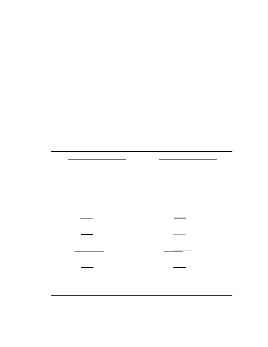
XC =
2πfC
4-48. Next, you must establish some values for the circuit. As you can see from the
calculations in Table 4-1, by doubling the frequency of the rectifier, you reduce the
impedance of the capacitor by one-half. This allows the AC component to pass through the
capacitor more easily. As a result, a full-wave rectifier output is much easier to filter than
that of a half-wave rectifier. Remember, the smaller the XC of the filter capacitor, in respect
to the load resistance, the better the filtering action. If load resistance is made small, the
load current increases, and the average value of output voltage (Eavg) decreases. The RC
discharge time constant is a direct function of the value of the load resistance. Therefore,
the rate of capacitor voltage discharge is a direct function of the current through the load.
The greater the load current, the more rapid the discharge of the capacitor, and the lower
the average value of output voltage. For this reason, the simple, capacitive filter is seldom
used with rectifier circuits that must supply a relatively large load current. Using the simple
capacitive filter in conjunction with a full-wave or bridge rectifier provides improved
filtering because the increased ripple frequency decreases the capacitive reactance of the
filter capacitor.
Table 4-1. Calculating Half-wave Rectifier and Full-wave Rectifier
FULL-WAVE RECTIFIER
HALF-WAVE RECTIFIER
FREQUENCY AT RECTIFIER
FREQUENCY AT RECTIFIER
OUTPUT: 60 Hz
OUTPUT: 120 Hz
VALUE OF FILTER CAPACITOR:
VALUE OF FILTER CAPACITOR:
30F
30F
LOAD RESISTANCE (RL): 10κΩ
LOAD RESISTANCE (RL): 10κΩ
1
1
XC =
XC =
2πfC
2πfC
.159
.159
XC =
XC =
fC
fC
.159
.159
XC =
XC =
60 x .000030
120 x .000030
.159
.159
XC =
XC =
.0018
.036
44.16Ω
88.3Ω
XC =
XC =
23 June 2005
TC 9-62
4-17


 Previous Page
