TC 9-62
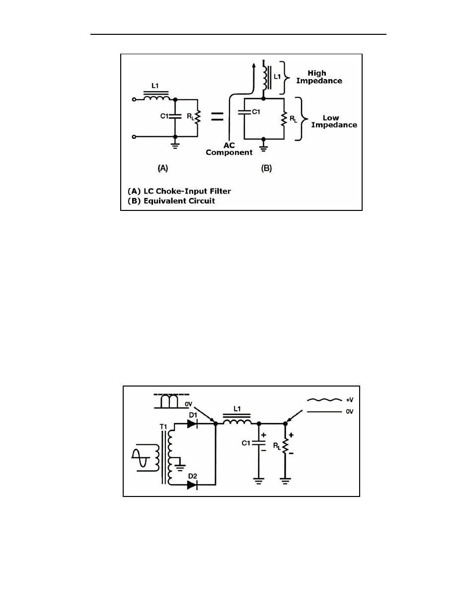
Figure 4-21. LC Choke-input Filter (Voltage Divider)
4-54. Figure 4-22 shows a complete cycle of operation for a full-wave rectifier circuit
used to supply the input voltage to the filter. The rectifier voltage is developed across the
capacitor (C1). The ripple voltage at the output of the filter is the alternating component of
the input voltage reduced in amplitude by the filter section. Each time the anode of a diode
goes positive with respect to the cathode, the diode conducts and C1 charges. Conduction
occurs twice during each cycle for a full-wave rectifier. For a 60-Hz supply, this produces
a 120-Hz ripple voltage. Although the diodes alternate (one conducts while the other is
nonconducting), the filter input voltage is not steady. As the anode voltage of the
conducting diode increases (on the positive half of the cycle), capacitor C1 charges (the
charge being limited by the impedance of the secondary transformer winding, the diode's
forward [cathode-to-anode] resistance, and the counter electromotive force developed by
the choke). During the nonconducting interval (when the anode voltage drops below the
capacitor charge voltage), C1 discharges through the load resistor (RL). Since the
components in the discharge path have a long time constant, C1 discharges more slowly
than it charges.
Figure 4-22. Filtering Action of the LC Choke-input Filter
4-20
TC 9-62
23 June 2005


 Previous Page
