______________________________________________________________ Solid State Power Supplies
effectiveness or filter resistors that have decreased in value, result in an excessive ripple
amplitude in the output of the supply.
Inductance-Capacitor Capacitor-Input Filter
4-81. The LC capacitor-input filter is one of the most commonly used filters. This type
of filter is used primarily in radio receivers, small audio amplifier power supplies, and in
any type of power supply where the output current is low and the load current is relatively
constant.
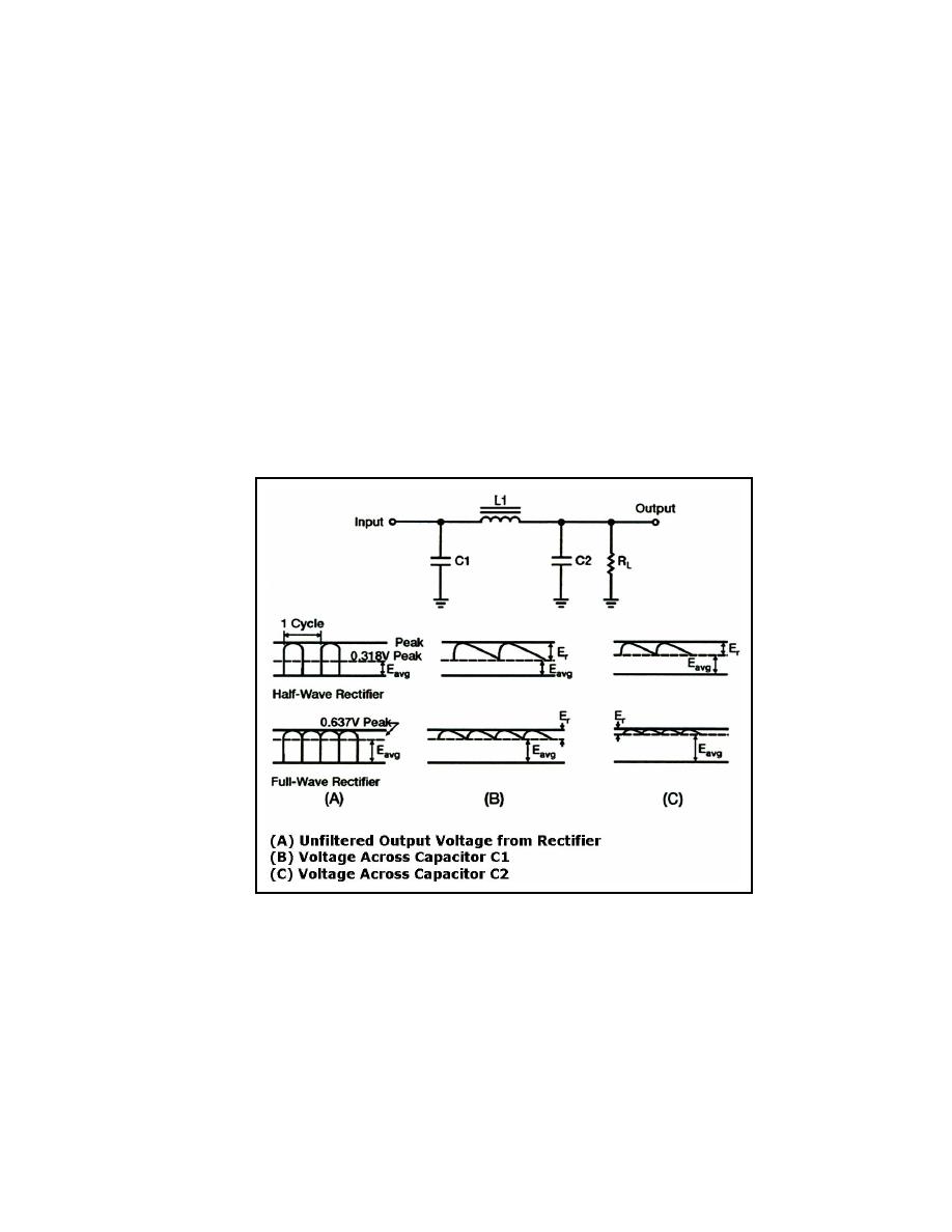
4-82. Figure 4-29 shows an LC capacitor-input filter and associated waveforms. Half-
wave and full-wave rectifier circuits are used to provide the input. The waveforms shown
in view (A) represent the unfiltered output from a typical rectifier circuit. Notice that the
average value of output voltage (Eavg), indicated by the dashed lines, for the half-wave
rectifier is less than half the amplitude of the voltage peaks. The average value of output
voltage (Eavg) for the full-wave rectifier is greater than half, but is still less than the peak
amplitude of the rectifier-output waveform with no filter connected across the output of the
rectifier circuit (which results in unfiltered output voltage). The waveform has a large value
of pulsating component (ripple) as compared to the average (or DC) component.
Figure 4-29. LC Filter and Waveforms
4-83. C1 reduces the ripple to a relatively low level (see Figure 4-29, view B). L1 and
C2 form the LC filter that reduces the ripple even further. L1 is a large value iron-core
high reactance to the ripple frequency. At the same time, C2 offers a very low reactance to
AC ripple. L1 and C2 form an AC voltage divider and because the reactance of L1 is much
higher than that of C2, most of the ripple voltage is dropped across L1. Only a slight trace
of ripple appears across C2 and the load (see Figure 4-29, view C).
23 June 2005
TC 9-62
4-27


 Previous Page
