______________________________________________________________ Solid State Power Supplies
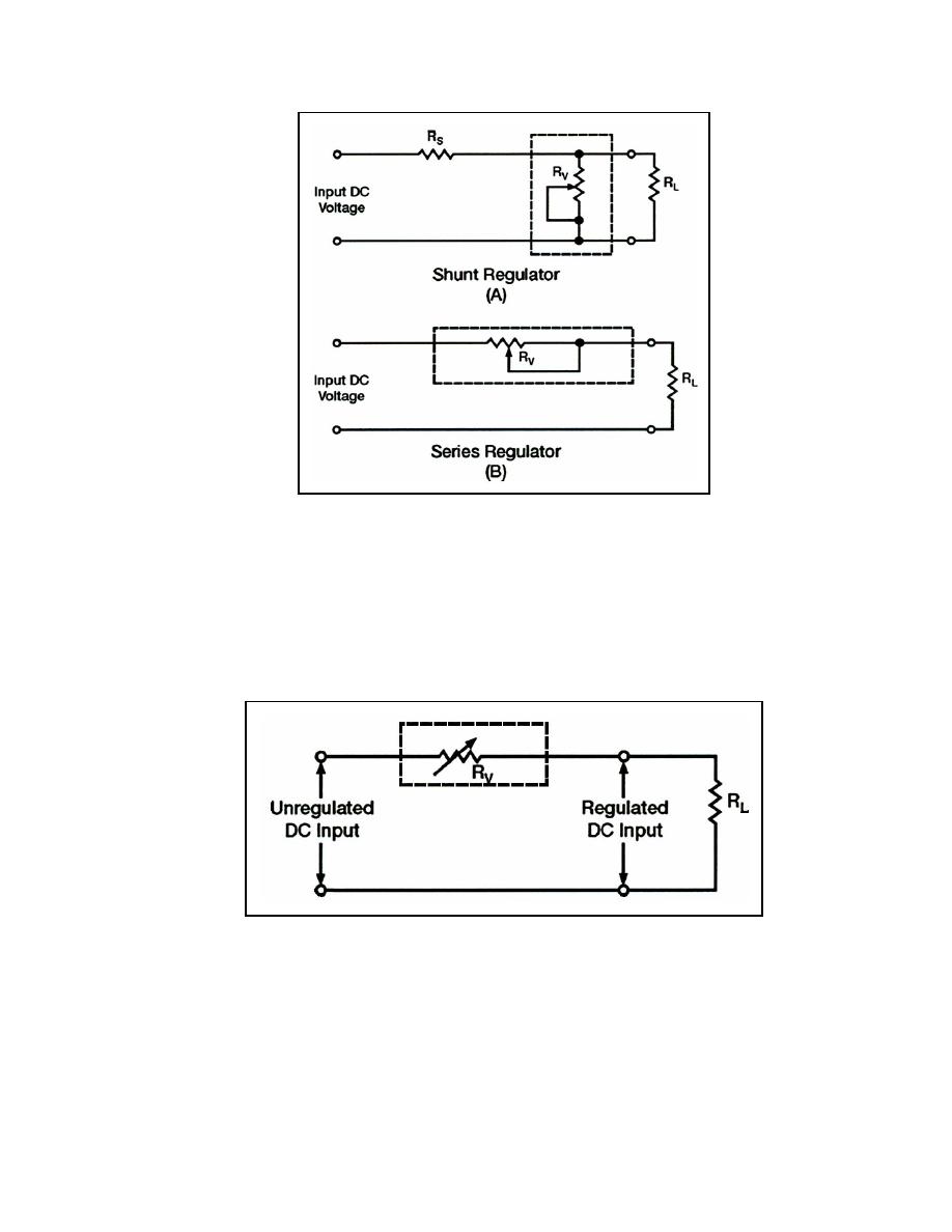
Figure 4-31. Simple Series and Shunt Voltage Regulators
4-98. The schematic drawing in Figure 4-31, view (A) is that of a shunt-type regulator. It
is called a shunt-type regulator because the regulating device is connected in parallel with
the load resistance. The schematic drawing in view (B) is that of a series regulator. It is
called a series regulator because the regulating device is connected in series with the load
resistance. Figure 4-32 shows the principle of series voltage regulation. Notice that the
with the load resistance.
Figure 4-32. Principle of Series Voltage Regulator
4-99. Remember that the voltage drop across a fixed resistor remains constant unless the
current flowing through it varies (increases or decreases). In a shunt regulator, see Figure
4-33, output voltage regulation is determined by the current through the parallel resistance
that the circuit is operating under normal conditions, that the input is 120 volts DC and that
the desired regulated output is 100 volts DC. For a 100-volt output to be maintained, 20
volts must be dropped across the series resistor (Rs). If you assume that the value of Rs is 2
23 June 2005
TC 9-62
4-31


 Previous Page
