______________________________________________________________ Solid State Power Supplies
4-104. So far only voltage regulators that use variable resistors have been explained.
However, this type of regulation has limitations. Obviously, the variable resistor cannot be
adjusted rapidly enough to compensate for frequent fluctuations in voltages. Since input
voltages fluctuate frequently and rapidly, the variable resistor is not a practical method for
voltage regulation. A voltage regulator that operates continuously and automatically to
regulate the output voltage without external manipulation is required for practical
regulation.
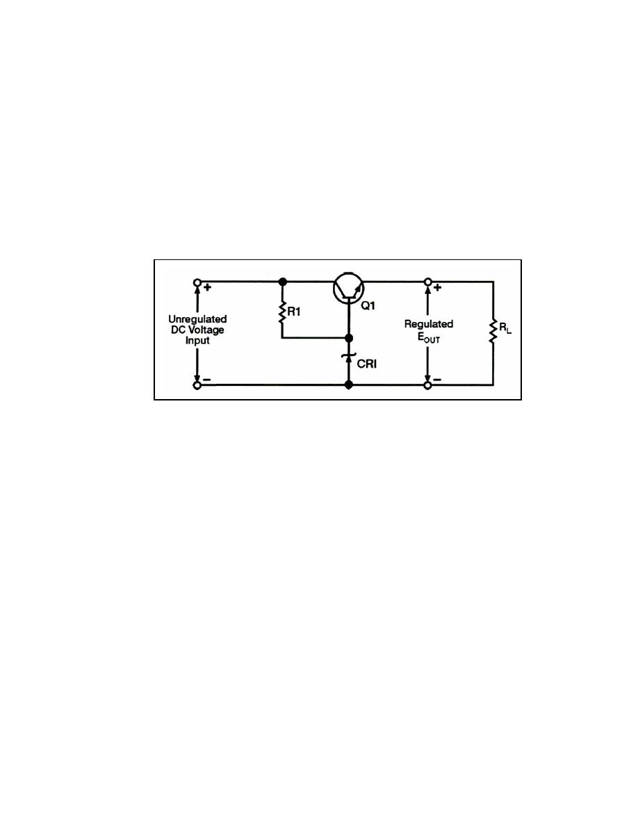
4-105. Figure 4-34 shows a schematic for a typical series voltage regulator. Notice that
this regulator has a transistor (Q1) in the place of the variable resistor found in
Figure 4-33. Since the total load current passes through this transistor, it is sometimes
called a "pass transistor." Other components that make up the circuit are the current
limiting resistor (R1) and the Zener diode (CR1).
Figure 4-34. Schematic of Series Voltage Regulator
4-106. Remember that a Zener diode blocks current until a specified voltage is applied.
Also that the applied voltage is called the breakdown or Zener voltage. Zener diodes are
available with different Zener voltages. When the Zener voltage is reached, the Zener
diode conducts from its anode to its cathode (with the direction of the arrow).
4-107. In this voltage regulator, Q1 has a constant voltage applied to its base. This voltage
is often called the reference voltage. As changes in the circuit output voltage occur, they
are sensed at the emitter of Q1, producing a corresponding change in the forward bias of
the transistor. In other words, Q1 compensates by increasing or decreasing its resistance in
order to change the circuit voltage division.
4-108. In Figure 4-35, voltages are shown to help you understand how the regulator
operates. The Zener used in this regulator is a 15-volt Zener. In this instance, the Zener or
breakdown voltage is 15 volts. The Zener establishes the value of the base voltage for Q1.
The output voltage will equal the Zener voltage minus a 0.7-volt drop across the forward
biased base-emitter junction of Q1 or 14.3 volts. Since the output voltage is 14.3 volts, the
voltage drop across Q1 must be 5.7 volts.
23 June 2005
TC 9-62
4-33


 Previous Page
