_______________________________________________________________________ Special Devices
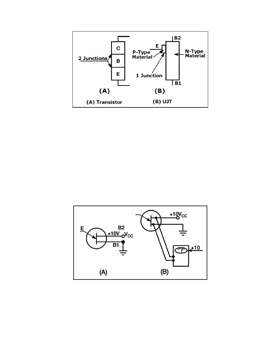
Figure 3-40. Transistor and UJT Structure
3-68. Figure 3-41, view (A), shows the normal bias arrangement for the UJT. A positive
10 volts is placed on base 2 and a ground on base 1. The area between base 1 and base 2
then acts as a resistor. If a reading were taken between base 1 and base 2, the meter would
indicate the full 10 volts (see Figure 3-41, view (B)). Theoretically, if one meter lead were
connected to base 1 and the other lead to some point between base 1 and base 2, the meter
could read some voltage less than 10 volts (Figure 3-42, view (A) shows this concept).
View (B) also shows the voltage levels at different points between the two bases. The
sequential rise in voltage is called a voltage gradient.
3-69. The emitter of the UJT can be viewed as the wiper arm of a variable resistor. If the
voltage level on the emitter is more positive than the voltage gradient level at the emitter-
base material contact point, then the UJT is forward biased. The UJT will conduct heavily
(almost a short circuit) from base 1 to the emitter. The manufacturer fixes the emitter in
position. The level of the voltage gradient therefore depends upon the amount of bias
voltage (see Figure 3-43).
Figure 3-41. UJT Biasing
23 June 2005
TC 9-62
3-25


 Previous Page
