_______________________________________________________________________ Antennas
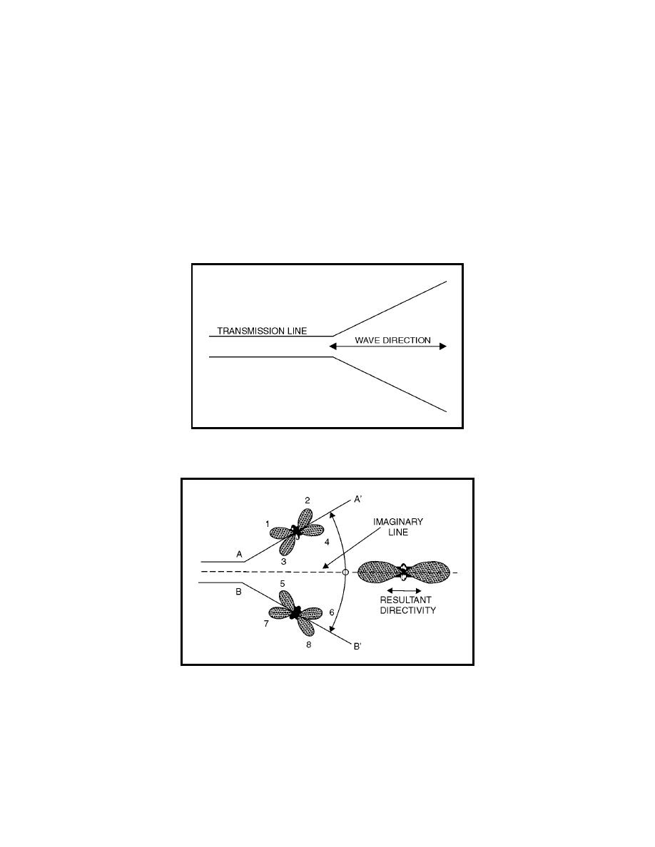
figure 4-36). Connecting the two-wire feed line to the apex of the V and
exciting the two sides of the V 180 degrees out of phase causes the lobes to
add along the line of the bisector and to cancel in other directions, as shown
in figure 4-37. The lobes are designated 1, 2, 3, and 4 on leg AA', and 5, 6, 7,
and 8 on leg BB'. When the proper angle between AA' and BB' is chosen,
lobes 1 and 4 have the same direction and combine with lobes 7 and 6,
respectively. This combination of two major lobes from each leg results in the
formation of two stronger lobes, which lie along an imaginary line bisecting
the enclosed angle. Lobes 2, 3, 5, and 8 tend to cancel each other, as do the
smaller lobes, which are approximately at right angles to the wire legs of the
figure 4-37.
Figure 4-36. Basic V Antenna
Figure 4-37. Formation of Directional Radiation from a Resonant V Antenna
Rhombic Antenna
4-164. The highest development of the long-wire antenna is the rhombic
antenna (see figure 4-38). It consists of four conductors joined to form a
rhombus, or diamond shape. The antenna is placed end to end and
4-49


 Previous Page
