TC 9-64 _________________________________________________________________________
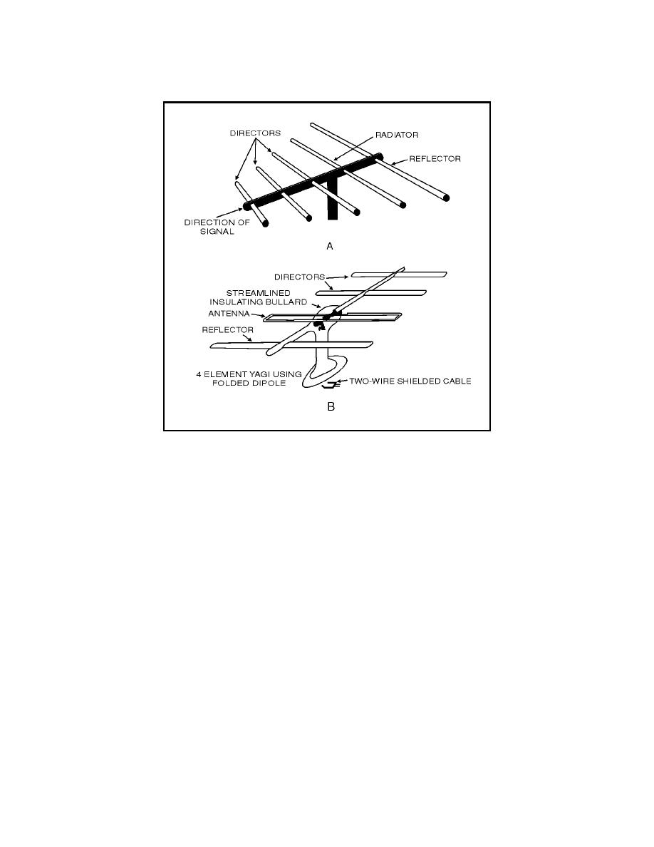
Figure 4-33. Yagi Antenna
4-154. Yagi antennas. An example of a multi-element parasitic array is
the yagi antenna (figure 4-33, views A and B). The spacings between the
elements are not uniform. The radiation from the different elements arrives
in phase in the forward direction, but out of phase by various amounts in the
other directions.
4-155. The director and the reflector in the yagi antenna are usually welded
to a conducting rod or tube at their centers. This support does not interfere
with the operation of the antenna. Because the driven element is center-fed,
it is not welded to the supporting rod. Using a folded dipole as the driven
element can increase the center impedance.
4-156. The yagi antenna shown in figure 4-33, view A, has three directors. In
general, the greater number of parasitic elements used, the greater the gain.
However, a greater number of such elements cause the array to have a
narrower frequency response as well as a narrower beam width. Therefore,
proper adjustment of the antenna is critical. The gain does not increase
directly with the number of elements used. For example, a three-element yagi
array has a relative power gain of 5 dB. Adding another director results in a
2 dB increase. Additional directors have less and less effect.
4-157. A typical yagi array used for receiving and transmitting energy is
shown with a support frame in figure 4-34. This antenna is used by the
military services. It operates at frequencies of from 12 to 50 megahertz and
4-46


 Previous Page
