TC 9-64 _________________________________________________________________________
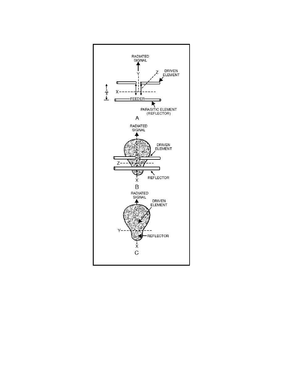
Figure 4-32. Patterns Obtained Using a Reflector with Proper Spacing
4-146. Because the voltage induced in the reflector is 180 degrees out of
phase with the signal produced at the driven element, a reduction in signal
strength exists behind the reflector. Because the magnitude of an induced
voltage never quite equals that of the inducing voltage, even in very closely
coupled circuits, the energy behind the reflector (minor lobe) is not reduced
to 0.
4-147. The spacing between the reflector and the driven element can be
reduced to about 15 percent of a wavelength. The parasitic element must be
4-44


 Previous Page
