TC 9-64 _________________________________________________________________________
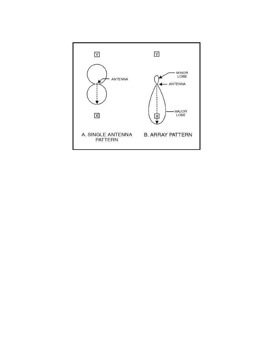
Figure 4-25. Single Antenna Versus Array
Major and Minor Lobes
4-115. The pattern shown in figure 4-25, view B has radiation concentrated in
two lobes. The radiation intensity in one lobe is considerably stronger than in
the other. The lobe toward point X is called a major lobe; the other is a minor
lobe. Because the complex radiation patterns associated with arrays frequently
contain several lobes of varying intensity, you should learn to use appropriate
terminology. In general, major lobes are those in which the greatest amount of
radiation occurs. Minor lobes are those in which the radiation intensity is least.
4-116. You have already learned about radiation patterns and directivity of
radiation. These topics are important to you because using an antenna with
an improper radiation pattern or with the wrong directivity will decrease the
overall performance of the system. In the following paragraphs, we discuss in
more detail the various types of directional antenna arrays mentioned earlier
in this chapter.
Collinear Array
4-117. The pattern radiated by the collinear array is similar to that
produced by a single dipole. The addition of the second radiator, however,
tends to intensify the pattern. Compare the radiation pattern of the dipole
(figure 4-26, view A) and the two-element antenna in view B. You will see
that each pattern consists of two major lobes in opposite directions along the
same axis, QQ1. There is little or no radiation along the PP1 axis. QQ1
represents the line of maximum propagation. You can see that radiation is
stronger with an added element. The pattern in view B is sharper, or more
directive, than that in view A. This means that the gain along the line of
maximum energy propagation is increased and the beam width is decreased.
4-34


 Previous Page
