_______________________________________________________________________ Antennas
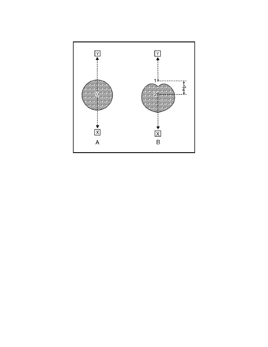
Figure 4-22. Phasing of Antenna in Free Space
4-106. Radiation from antenna 2 toward receiving location Y will reach
antenna 1 after one-quarter cycle. The energy in antenna 1 was one-quarter
cycle behind that of antenna 2 to begin with; therefore, the radiation from
antenna 1 toward receiving point Y will be exactly 180 degrees out of phase
with that of antenna 2. As a result, the radiation fields will cancel and there
will be no radiation toward Y.
4-107. At receiving points away from the line of radiation, phase differences
occur between 0 and 180 degrees, producing varying amounts of energy in
that direction. The overall effect can be seen in the radiation pattern
illustrated in view B. The physical phase relationship caused by the
wavelength spacing between the two elements, as well as the phase of the
currents in the elements, has acted to change the radiation pattern of the
individual antennas.
Stub Phasing
the same transmitter were 90 degrees out of phase. Sections of transmission
line, called stubs, are frequently used for this purpose. These stubs can be
adjusted to produce any desired phase relationship between connected
elements.
4-109. When two collinear half-wave elements are connected directly so their
currents are in the same phase, the effect is the same as that of a full-wave
antenna, as shown in figure 4-23, view A. The current in the first one-half
wavelength is exactly 180 degrees out of phase with that in the second one-
half wavelength. This is the opposite of the desired condition. In the
illustration, arrows are used to indicate the direction of current flow in the
4-31


 Previous Page
