TC 9-64 _________________________________________________________________________
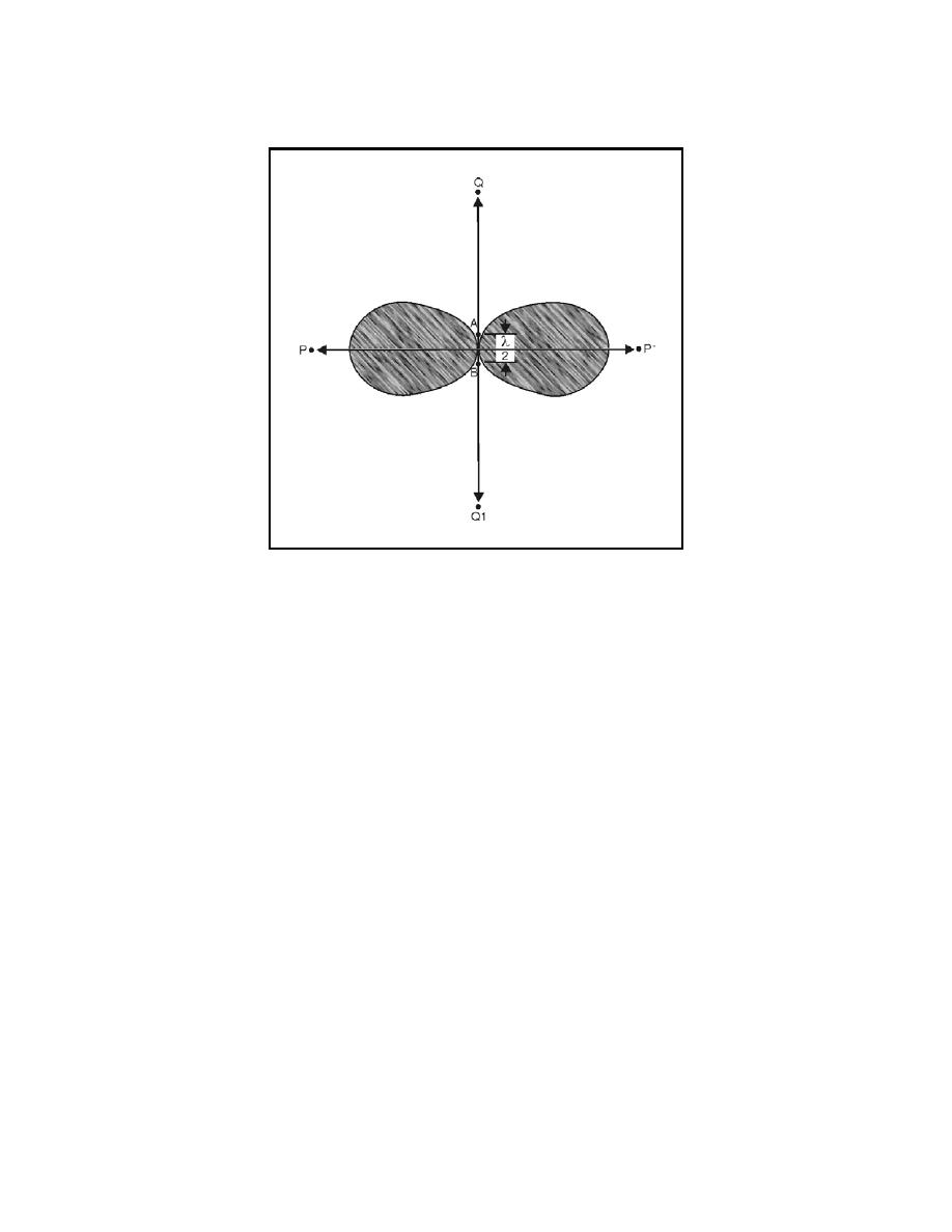
Figure 4-28. Parallel Elements in Phase
4-126. Next consider a wavefront traveling toward point Q from antenna B.
By the time it reaches antenna A, one-half wavelength away, one-half cycle
has elapsed. Therefore energy from antenna B meets the energy from
antenna A 180 degrees out of phase. As a result, the energy moving toward
point Q from the two sources cancels. In a like manner, radiation from
antenna A traveling toward point Q1 meets and cancels the radiation in the
same direction from antenna B. As a result, little propagation takes place in
either direction along the QQ1 axis. Most of the energy is concentrated in
both directions along the PP1 axis. When both antenna elements are fed from
the same source, the result is the basic broadside array.
4-127. When more than two elements are used in a broadside arrangement,
they are all parallel and in the same plane, as shown in figure 4-27, view B.
Current phase, indicated by the arrows, must be the same for all elements.
The radiation pattern shown in figure 4-27, view C, and is always
bidirectional. This pattern is sharper than the one shown in figure 4-28
because of the additional two elements. Directivity and gain depend on the
number of elements and the spacing between them.
4-128. Gain and directivity. The physical disposition of dipoles operated
broadside to each other allows for much greater coupling between them than
can occur between collinear elements. Moving the parallel antenna elements
closer together or farther apart affects the actual impedance of the entire
array and the overall radiation resistance as well. As the spacing between
broadside elements increases, the effect on the radiation pattern is a
sharpening of the major lobes. When the array consists of only two dipoles
spaced exactly one-half wavelength apart, no minor lobes are generated at
all. Increasing the distance between the elements beyond that point,
4-38


 Previous Page
