___________________________________________________ Principles of Transmission Lines
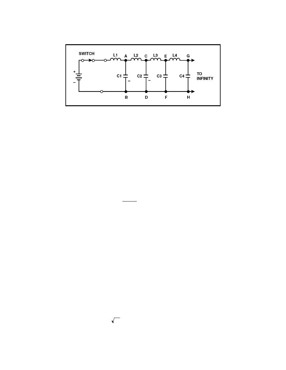
Figure 3-23. DC Applied to an Equivalent Transmission Line
3-78. Because none of the charge is lost, the total charge leaving the battery
during T is equal to the total charge on the line. Therefore:
Q = IT = CE
3-79. As each capacitor accumulates a charge equal to CE, the voltage across
each inductor must change. As C1 in figure 3-23 charges to a voltage of E,
point A rises to a potential of E volts while point B is still at zero volts. This
makes E appear across L2. As C2 charges, point B rises to a potential of E
volts as did point A. At this time, point B is at E volts and point C rises.
Thus, there is a continuing action of voltage moving down the infinite line.
3-80. In an inductor, these circuit components are related, as shown in the
formula--
∆I
E=L
(
)
∇T
3-81. 1-79. This shows that the voltage across the inductor is directly
proportional to inductance and the change in current, but inversely
proportional to a change in time. Because current and time start from zero,
the change in time (∆T) and the change in current (∆I) are equal to the final
time (T) and final current (I). For this case the equation becomes:
ET = LI
3-82. If voltage E is applied for time (T) across the inductor (L), the final
current (I) will flow. The following equations show how T, L, and C are related:
ET = LI
IT = CE
3-83. For convenience, you can find T in terms of L and C by multiplying the
left and right members of each of the above equations, and solving for T, as
follows:
(IT)(ET) = (CE)(LI)
EIT2 = LCEI
T2 = LC
T= LC
3-25


 Previous Page
