TC 9-64 _________________________________________________________________________
AC Applied to an Infinite Line
3-69. An RF line displays similar characteristics when an AC voltage is
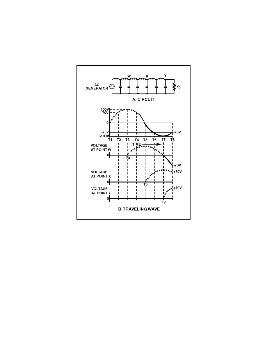
applied to its sending end or input terminals. In figure 3-21, view A, an AC
voltage is applied to the line represented by the circuit shown.
Figure 3-21. AC Applied to an Equivalent Transmission Line
3-70. In figure 3-21, view B, the generator voltage starts from zero (T1) and
produces the voltage shown. As soon as a small voltage change is produced, it
starts its journey down the line while the generator continues to produce new
voltages along a sine curve. At T2 the generator voltage is 70 volts. The
voltages still move along the line until, at T3, the first small change arrives
at point W, and the voltage at that point starts increasing. At T5, the same
voltage arrives at point X on the line. Finally, at T7, the first small change
arrives at the receiving end of the line. Meanwhile, all the changes in the sine
wave produced by the generator pass each point in turn. The amount of time
required for the changes to travel the length of the line is the same as that
required for a DC voltage to travel the same distance.
3-22


 Previous Page
