TC 9-62
3-91. The operation of the MOSFET, or IGFET, is basically the same as the operation of
the JFET. The current flow between the source and drain can be controlled by using either
one of two methods or by using a combination of the two methods. In one method the drain
voltage controls the current when the gate potential is at zero volts. A voltage is applied to
the gate in the second method. The gate voltage that affects the current flow in the channel
by either depleting or enhancing the number of current carriers available forms an electric
field. Remember, a reverse bias applied to the gate depletes the carriers and a forward bias
enhances the carriers. The polarity of the voltages required to forward or reverse bias a
MOSFET depends upon whether it is of the P-channel type or the
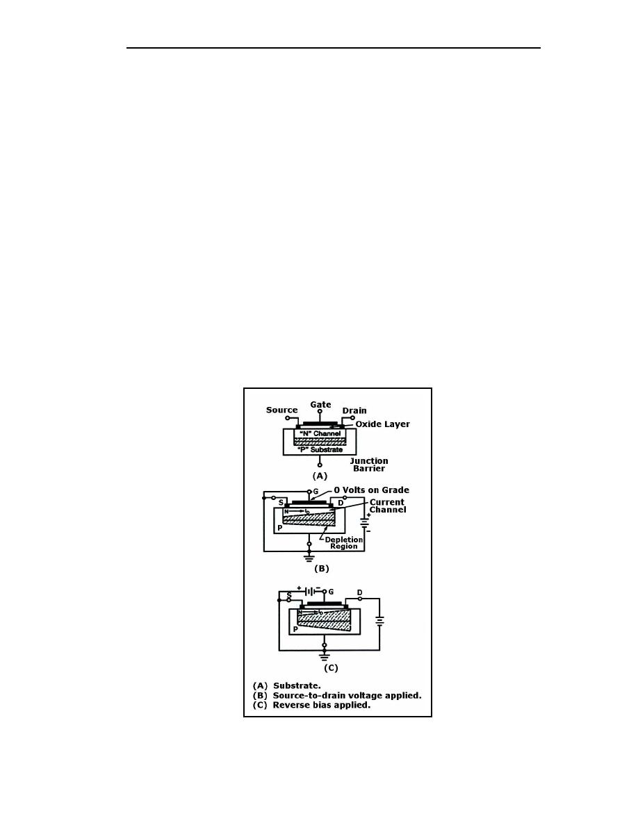
N-channel type. Figure 3-54, views (A), (B), and (C) shows the effects of reverse-bias
voltage on a MOSFET designed to operate in the depletion mode. The amount of reverse
bias applied has a direct effect on the width of the current channel and thereby, the amount
of drain current (ID).
3-92. Figure 3-55 shows the effect of forward bias on an enhancement mode N-channel
MOSFET. In this case, a positive voltage applied to the gate increases the width of the
current channel and the amount of drain current (ID).
3-93. Another type of MOSFET is the induced-channel type MOSFET. Unlike the
MOSFETs covered so far, the induced-channel type has no actual channel between the
source and the drain. The induced channel MOSFET is constructed by making the channel
of the same type material as the substrate, or the opposite of the source and the drain
material (see Figure 3-56). The figure also shows that the source and the drain are of P-
type material and the channel and the substrate are of N-type material.
Figure 3-54. Effects of Reverse-bias Voltage (MOSFET in Depletion Mode)
3-34
TC 9-62
23 June 2005


 Previous Page
