system (par 7b) or to the end of the branch line off point C.) By allowing,
roughly, a fourth or a fifth of the total voltage drop for this particular section,
you should have enough drop left for the later sections. Using a No. 4 wire, the
actual voltage drop resulting is approximately 1.1 percent. The results of these
computations should be tabulated as shown in figure 17.
(4) Section BC.
The load carried by this section is the sum of the loads
beyond point B or 6.82 KVA.
The distance is 300 feet.
Allow up to 2 percent
voltage drop in this section.
From figure 9 a No. 6 wire may be used, which
actually drops the voltage by 1.8 percent.
The cumulative voltage drop to this
point is now 1.1 + 1.8 = 2.9 percent.
(5) Section CD.
The load is 4.57 KVA; the length is 150 feet.
Since the
cumulative voltage drop to point C is 2.9 percent, you are still 2.1 percent under
the specified maximum.
Actually, this is quite a bit of allowance for this last
section and, consequently, a very small economical wire could be selected.
However, a No. 8 is the smallest allowable size. Hence, using this for section CD
will result in an additional 1.0 percent voltage drop making the cumulative drop to
point D 1.1 +1.8 + 1.0 = 3.9 percent. Figure 17 shows the complete tabulation for
the feeder line.
As shown, the wire sizes selected have created a total voltage
drop of 3.9 percent to point D. Therefore, there is an allowable 1.1 percent drop
for each group of buildings being served by the branch lines off point D. The next
usual step is to determine the size of wire for the branch circuits at the end of
the feeder line.
These last branches are critical because they will have the
largest accumulated voltage drop.
(6) Branch line design.
Figure 18 shows the group of buildings (16 through
22) for which wire size will be determined next. Design of these branches varies
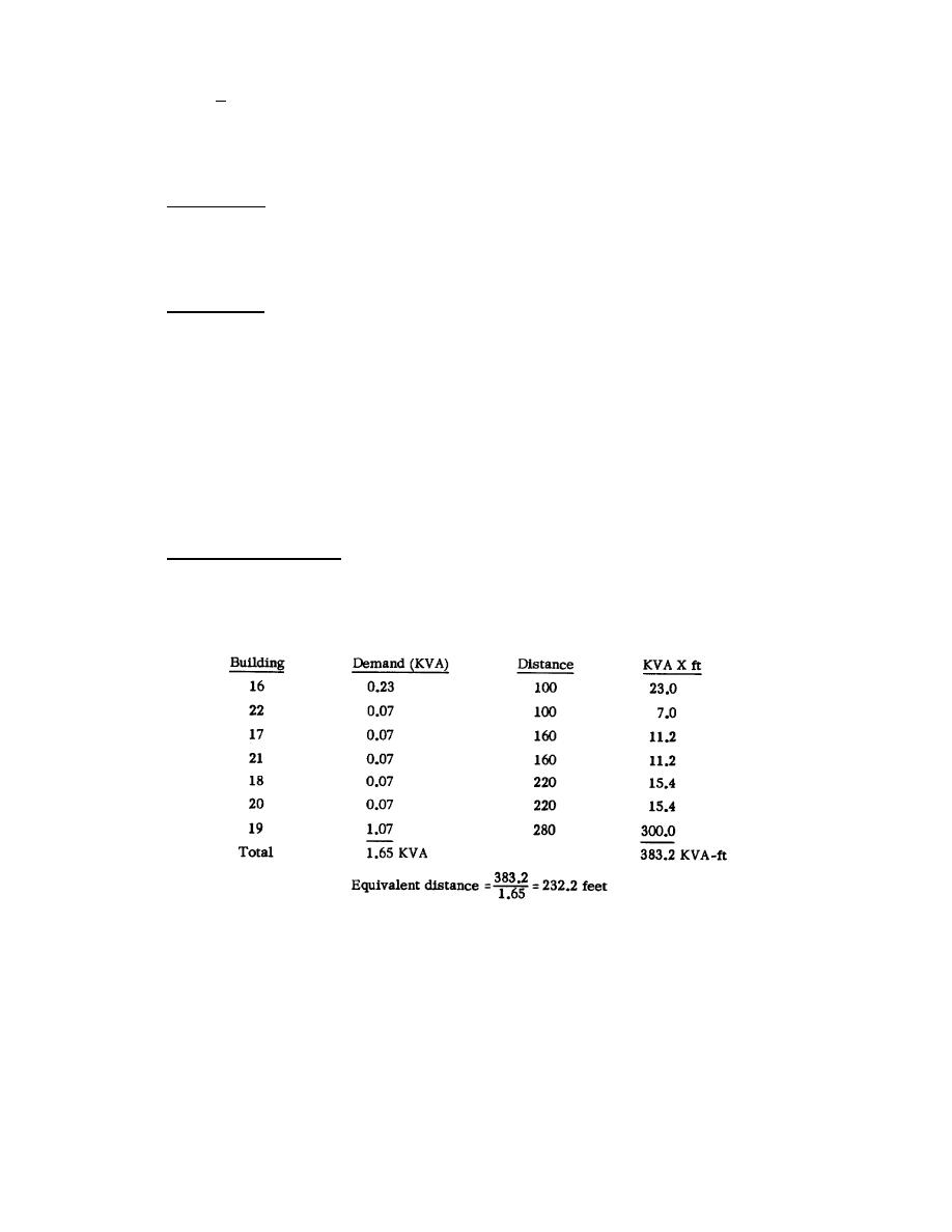
slightly from that for the feeder in that the equivalent distance of the branch
must be computed. The equivalent distance is the ratio of total KVAX ft to total
KVA and is computed as follows:
Since you had a 3.9 percent cumulative voltage drop to point D, there is an
allowable 1.1 percent remaining for this particular branch. Figure 9 is now used
by entering on it a load of 1.65 KVA, a distance of 232.2 feet, and a 1.1 percent
voltage drop. Using a No. 8 wire, the voltage drop induced in the branch line will
be approximately 0.5 percent. Hence the total voltage drop from the generator to
building 19 is 3.9 + 0.5 = 4.4 percent, which is within specifications.
2-24


 Previous Page
