a. Load estimation.
Figure 14 is
sections into which it will be divided
an estimate of the electrical load for
for the purpose of determining its
this portion of the installation. The
wire sizes.
connected lighting and power loads
were given as shown.
A demand factor
(1) Section GA.
This section
was applied and the total demand
carries such a large load for such a
computed for each structure. A three-
short distance that the voltage drop
phase, four-wire, 127/220V system will
will not be the controlling factor.
be
used.
The
sum
of
all
the
Rather, the current and the load will
individual demands is 85.45 KVA.
determine the wire size. From table 1
a No. 8 wire can carry up to 29 KVA
b. Generator
selection
and
without exceeding the current carrying
location.
The total demand load has
capacity of the wire.
Use a No. 8
been estimated as 85.45 KVA. Applying
wire for section GA.
a
generator
factor
of
0.85,
the
required generator capacity will be:
(2) Section
GO.
Again
the
85.45 x 0.85 = 72.6 KVA. Depending on
current and the load control the
availability, the following generator
required size.
From table 1 a No. 2
combinations can be employed:
wire can carry up to 69 KVA without
exceeding
the
current
carrying
Three 60 KW generators
capacity of the wire.
Use a No. 2
wire for section GO.
One 60 KW; one 45KW; and one 15
KW generator
(3) Section GB.
This section of
wire is carrying the bulk of the load
Two 100 KW generators
to the right of the generator, or
12.10 KVA.
The section is 150 feet
Four 30 KW generators
long. From the curves of figure 9 the
appropriate wire size should be a No.
The generators should be located close
4, assuming that to point B you
to buildings 1 and 2 which constitute
have
allowed,
say,
a
1
percent
the largest demand loads.
voltage
drop.
(Keep
in
mind
that you are allowed a 5 percent
c. Wiring layout. Buildings should
total
drop
to
the
end
of
the
be grouped in order to facilitate the
determination of the feeder and branch
lines.
For example, buildings 3, 4,
and 5 can be grouped and served by one
branch line.
Figure 15 shows one
method of laying out the feeder line
and is branches. Supporting poles are
spaced 150 feet apart.
Branch loads
are shown for each line.
d. Wire-size determinations.
The
maximum allowable voltage drop for the
system is 5 percent.
Beginning with
the
feeder
line,
the
system
is
designed in sections.
That is, the
section from the generator to building
No. 1 may require a certain size of
wire while the section of line to
building No. 2 may require a much
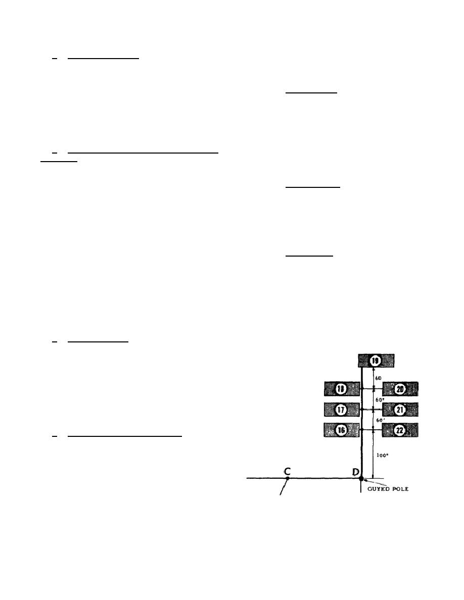
Figure 18.
Branch line design.
larger wire.
Figure 16 is a diagram
of the feeder showing the various
2-23


 Previous Page
