second-order, Class I net. The length closures, as compared to these lines or measured
baselines, must not exceed 1 part in 20,000 after all side and angle conditions have been
satisfied.
(1) Second-order, Class II triangulation is used to subdivide areas of higher control and to
provide networks for mapping, cadastral, and local surveys. Second-order, Class II triangulation must
start from and tie to lines of a first-order triangulation net or to lines of an adjusted net of second-order,
Class I or Class II. Length closures, as compared to these lines or measured baselines, must not exceed
1 part in 10,000 after all side and angle conditions have been satisfied.
(2) The 0.2-second theodolite is also used for second-order, Class I and Class II triangulation.
Observations are made at night using a 1.0-theodolite and signal lamps. Daylight observations using
heliotropes are also acceptable.
(3) The methods used in the observation of second-order, Class I and Class II, are designed to
give a maximum triangle closure of 5 seconds, with an average triangle closure for the net that does
not exceed the required average of 1.5 seconds for Class I or 3 seconds for Class II.
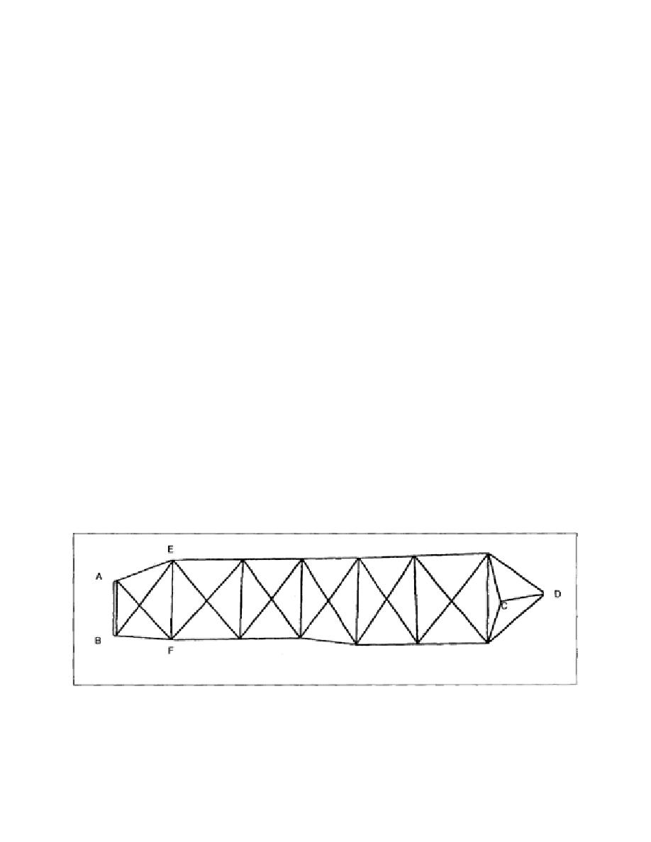
2-35. A Typical Triangulation Net. A typical triangulation net is shown in Figure 2-2. In first-order
triangulation, the known lines AB and CD are always baselines measured to such a precision as to
ensure that errors do not exceed 1 part in 300,000. For second-order triangulation, the known lines such
as AB and CD are either second-order baselines or adjusted lines of first-order triangulation. The
measured baseline AB is the known length. Once all the angles are observed, use the law of sines to
compute the lengths of the other lines in the figure. There are various ways of computing line EF, such
as through the triangle ABE, as shown in Figure 2-3. After computing the distance BE, which is then
used as the known line of the triangle BEF, line EF is computed. Another route to compute the length of
EF is through the triangles AFB and AFE. One of the routes is geometrically superior to the other,
depending on the angles used. Carry this system through from one figure to another until the next base
(CD) is reached. Obtain the check on the discrepancy between the measured length of that line and its
length as computed through the triangulation net from the preceding base (AB).
Figure 2-2. A Typical Triangulation Net
EN0593
2-20


 Previous Page
