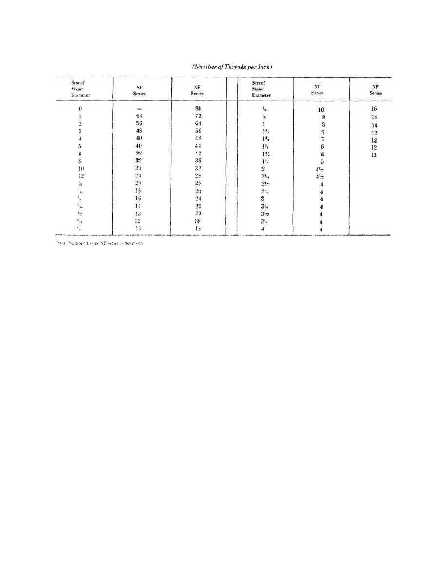
Table 2-6. American National Coarse (NO and National Fine (NF) Series
rivet symbols are shown in figure 2-31. Note that the
arrow, together with dimensions and other data, form
rivet head diameter is used to represent shop rivets
the welding symbol. The assembled welding symbol
and the rivet shank diameter to represent field rivets.
consists of the eight elements listed below, or such of
The symbol for field rivets indicates a hole in which
these elements as are necessary. The elements of the
rivets are to be placed. The intersection of pitch and
welding symbol have standard locations with respect
gage lines, represented by centerlines on detail
to each other as shown in figure 2-35.
drawing made to small scale, shows the placement of
the rivets.
(1) Reference line. This is the base for all
data and symbols comprising the welding symbol.
Standard forms of rivet heads are shown in figure 2-
32.
(2) Arrow.
The arrow points to the
location of the weld.
c. Welding. Welding is used in the rear area
as a method permanent joint between two metal parts.
This symbol
(3) Basic weld symbol.
Welding requires a great amount of equipment and,
designates the type of weld. Its location on the
therefore, has only limited use in the front areas.
reference line indicates the side of the object to be
Welding has its own language of symbols for use on
welded; that is, arrow side, other side, or both sides.
drawings. The welding symbol is a composite of
symbols and data indicating the requirements of a
(4) Dimensions and other data. The
given weld. As you can see in figure 2-33, the basic
information provided by this element of the welding
welding symbol is simply a reference line and an
symbol is given on figure 2-35, identified by the
arrow. This basic welding symbol serves as the base
symbols S, R, and (N).
on which all symbol information is placed in standard
locations. Symbols used to indicate the type of weld
(5) Supplementary symbols. This shows
(called basic weld symbols) and supplementary weld
the supplementary weld symbols (fig 2-34). The
symbols are shown in figure 2-34. The weld symbols
supplementary symbols on figure 2-35 indicate a
in their respective positions on the reference line and
field weld, to weld all around,
78


 Previous Page
