_______________________________________________________________________ Antennas
4-77. Radiation pattern of a doublet. The doublet is the simplest form of a
practical antenna. Its radiation pattern can be plotted in the same way as the
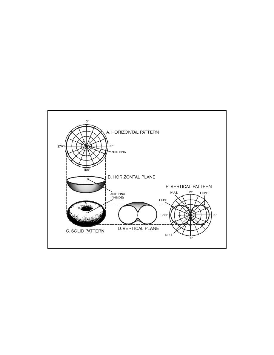
radiation pattern of the flashlight shown in figure 4-13. Figure 4-15
illustrates the development of vertical and horizontal patterns for a doublet.
This is not a picture of the radiation, but three-dimensional views of the
pattern itself that the radiation makes. In three views (views B, C, and D),
the pattern resembles a doughnut. From the dimensions in these views, two
types of polar-coordinate patterns can be drawn: horizontal and vertical. The
horizontal pattern shown in view A is derived from the solid pattern shown in
view C by slicing it horizontally. This produces view B, which is converted to
the polar coordinates seen in view A. The horizontal pattern illustrates that
the radiation is constant in any direction along the horizontal plane.
Figure 4-15. Development of Vertical and Horizontal Pattern
4-78. A vertical pattern shown in figure 4-15, view E is depicted from the
drawing of the vertical plane (view D) of the radiation pattern shown in view
C. The radiation pattern in view C is sliced in half along a vertical plane
through the antenna. This produces the vertical plane pattern shown in view
D. Note how the vertical plane in view D of the radiation pattern differs from
the horizontal plane in view B. The vertical pattern in view E exhibits two
lobes and two nulls. The difference between the two patterns is caused by two
facts: (1) no radiation is emitted from the ends of the doublet; and
(2) maximum radiation comes from the doublet in a direction perpendicular
to the antenna axis. This type of radiation pattern is both nondirectional (in a
horizontal plane) and directional (in a vertical plane).
4-23


 Previous Page
