_______________________________________________________________________ Antennas
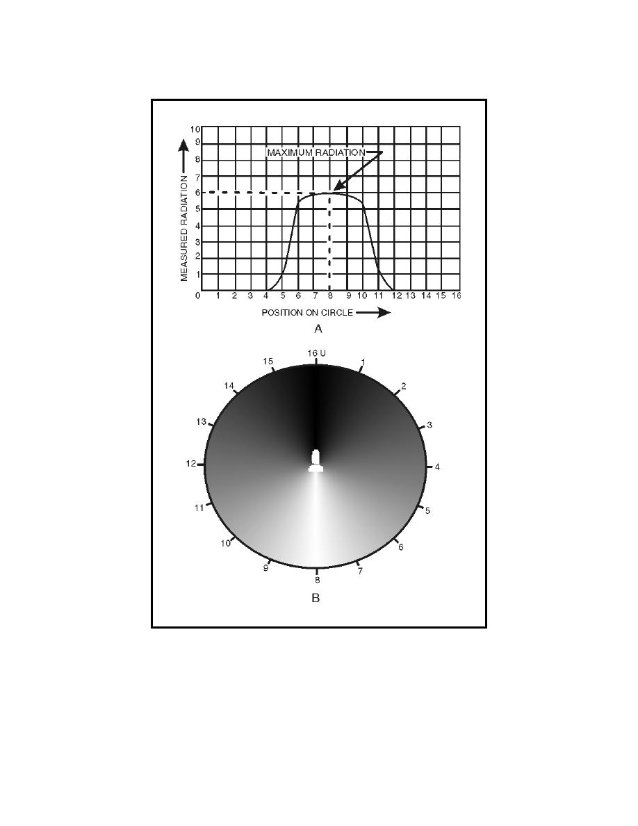
Figure 4-12. Anisotropic Radiator
4-65. Directly behind the flashlight (position 0) the radiation measured is
minimum. Accordingly, a 0 value is assigned to this position in the
rectangular-coordinate graph (figure. 4-12, view A). This radiation remains at
minimum until position 4 is reached. Between positions 4 and 6, the
measuring device enters the flashlight beam. You can see this transition from
darkness to brightness easily in view B. Radiation is fairly constant between
4-19


 Previous Page
