_____________________________________________________________________ Special Amplifiers
7-128. So far the control circuit of the magnetic amplifier has only been shown with DC
applied to it. Magnetic-amplifier control circuits should accept AC input signals as well as
DC input signals. As shown earlier in Figure 7-31, a saturable-core reactor has an ideal
operating point. Some DC must always be applied to bring the saturable core to that
operating point. This DC is called BIAS. The most effective way to apply bias to the
saturable core and also allow AC input signals to control the magnetic amplifier is to use a
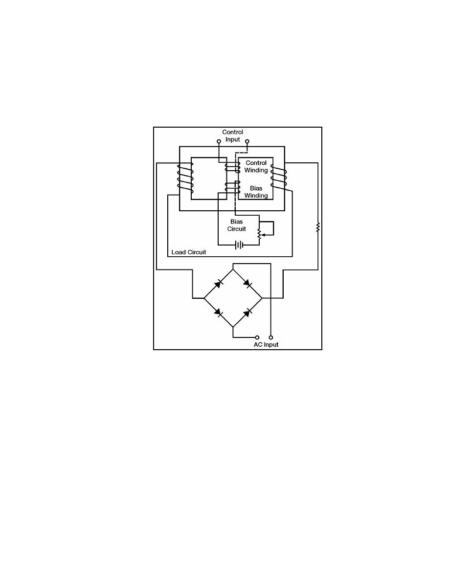
bias winding. Figure 7-37 shows a full-wave magnetic amplifier with a bias winding.
Figure 7-37. Full-wave Magnetic Amplifier With Bias Winding
7-129. Figure 7-37 shows the circuit where the bias circuit is adjusted to set the saturable-
core reactor at the ideal operating point. Input signals, represented by the AC source
symbol, are applied to the control input. The true power of the load circuit is controlled by
the control input signal (AC).
7-130. Figure 7-38 shows the block diagram symbol for a magnetic amplifier. The
triangle is the general symbol for an amplifier. The saturable-core reactor symbol in the
center of the triangle identifies the amplifier as a magnetic amplifier. Notice the input and
output signals shown. The input signal is a small-amplitude, low-power AC signal. The
output signal is a pulsating DC with an amplitude that varies. This variation is controlled
by the input signal and represents a power gain of 1,000.
7-131. Some magnetic amplifiers are designed so AC goes through the load rather than
pulsating DC. You can do this by placing the load in a different circuit position with
respect to the rectifier. The principle of the magnetic amplifier remains the same; that is,
control current still controls load current.
23 June 2005
TC 9-62
7-47


 Previous Page
