_____________________________________________________________________ Special Amplifiers
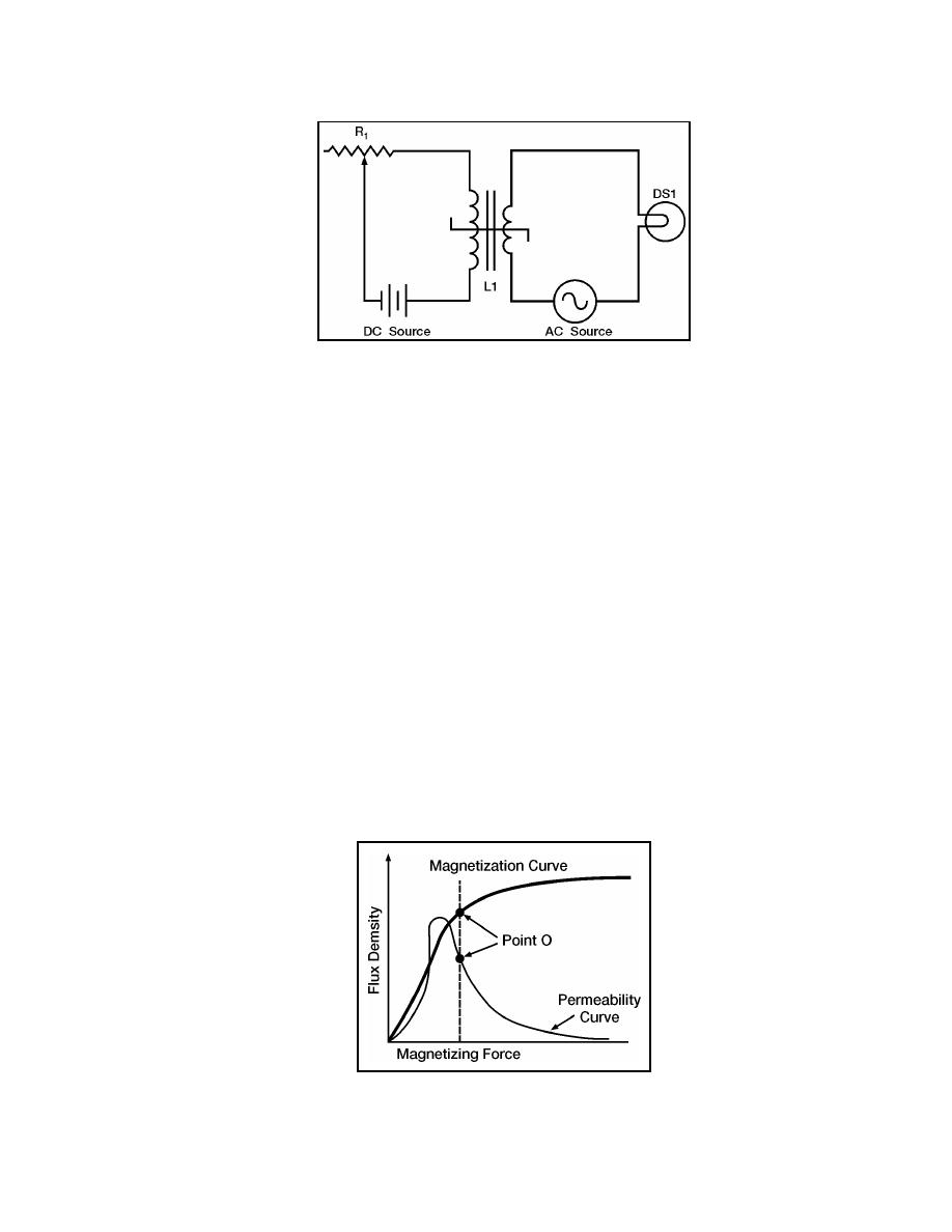
Figure 7-30. Schematic Diagram of a Simple Saturable-core Reactor
7-117. You now have seen the basic operation of a saturable-core reactor. There is one
more area to discuss before moving on to the circuitry of a magnetic amplifier. There is a
point upon the magnetization curve where the saturable-core reactor should be operated.
The ideal operating point is the place in which a small increase in control current will cause
a large increase in output power and a small decrease in control current will cause a large
decrease in output power. This point is on the flattest portion of the permeability curve
(after its peak). Figure 7-31 shows the magnetization and permeability curves for a
saturable-core reactor with the ideal operating point (point "0") indicated. Notice point "0"
on the magnetization curve. The portion of the magnetization curve where point "0" is
located is called the KNEE OF THE CURVE. The knee of the curve is the point of
maximum curvature. It is called the "knee" because it looks like the knee of a leg that is
bent. Saturable-core reactors and magnetic amplifiers should be operated on the knee of the
magnetization curve.
7-118. When the saturable-core reactor is set at the knee of the magnetization curve, any
small increase in control current will cause a large increase in load current. Any small
decrease in control current will cause a large decrease in load current. That is why point
"0" is the ideal operating point, because small changes in control current will cause large
changes in load current. In other words, the saturable-core reactor can amplify the control
current. However, a saturable-core reactor is not a magnetic amplifier. Later you will learn
how a magnetic amplifier differs from a saturable-core reactor. First you should know a
few more things about the saturable-core reactor.
Figure 7-31. Magnetization and Permeability Curves With Operating Point
23 June 2005
TC 9-62
7-41


 Previous Page
