TC 9-62
7-111. You have now seen how a change in the magnetizing force causes a change in
permeability. Now we will see how you change the magnetizing force. Magnetizing force
is a function of ampere-turns. An ampere-turn is the magnetomotive force developed by
1 ampere of current flowing in a coil of one turn. If you increase the ampere-turns of a coil,
the magnetizing force increases. Since it is not practical to increase the number of turns,
the easiest way to accomplish this is to increase the current through the coil.
7-112. If you increase the current through a coil, you increase the ampere-turns. By
increasing the ampere-turns you increase the magnetizing force. At some point, this causes
a decrease in the permeability of the core. With the permeability of the core decreased, the
inductance of the coil decreases. As already stated, a decrease in the inductance causes an
increase in power through the load. A device that uses this arrangement is called a
SATURABLE-CORE REACTOR or SATURABLE REACTOR.
SATURABLE-CORE REACTOR
7-113. A saturable-core reactor is a magnetic-core reactor (coil) whose reactance is
controlled by changing the permeability of the core. To change the permeability of the
core, vary a unidirectional flux (flux in one direction) through the core.
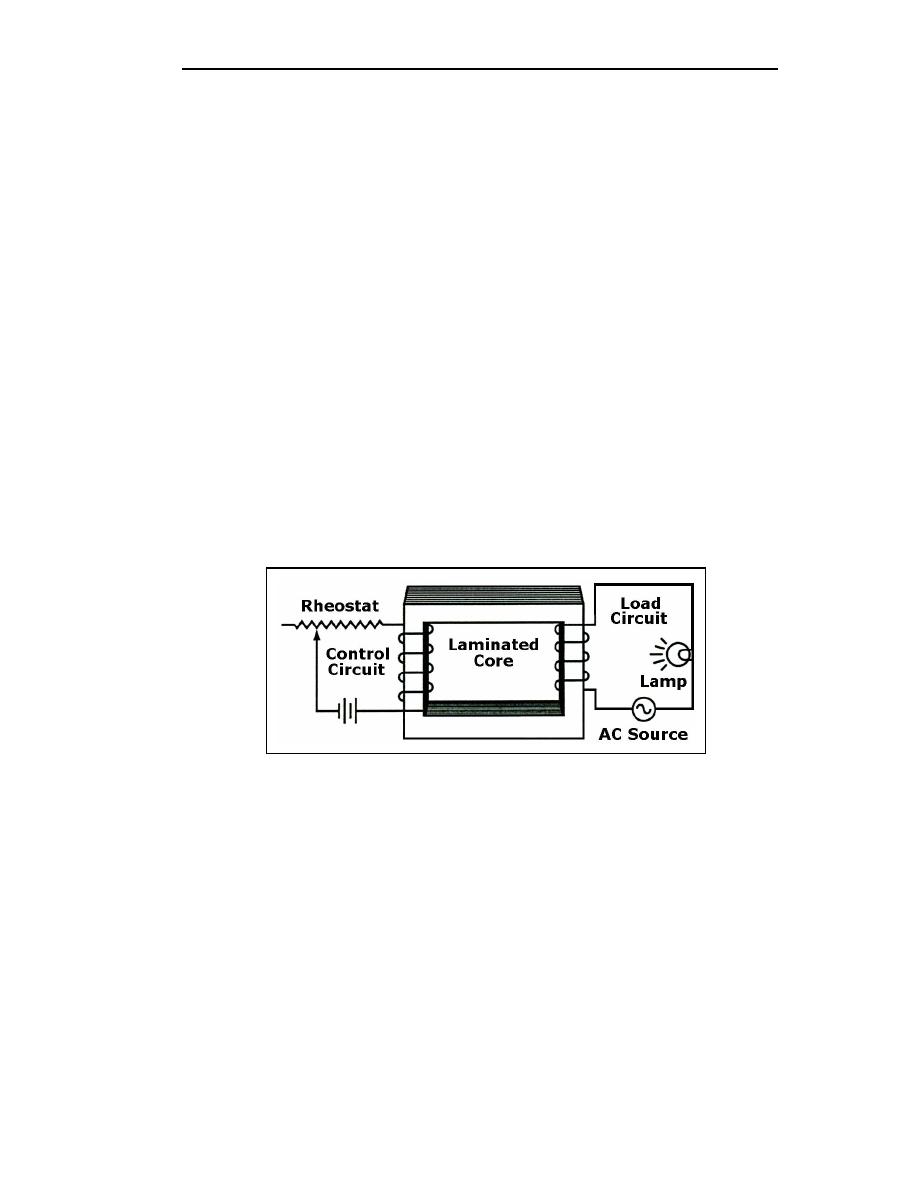
7-114. Figure 7-29 shows a saturable-core reactor that is used to control the intensity of a
lamp. Notice that two coils are wound around a single core. The coil on the left is
connected to a rheostat and a battery. This coil is called the control coil because it is part of
the control circuit. The coil on the right is connected to a lamp (the load) and an AC
source. This coil is called the load coil because it is part of the load circuit.
Figure 7-29. Simple Saturable-core Reactor Circuit
7-115. As the wiper (the movable connection) of the rheostat is moved toward the right,
there is less resistance in the control circuit. With less resistance, the control-circuit current
increases. This causes the amount of magnetism in the core to increase and the inductance
of the coil in the load circuit to decrease (because the core is common to both coils). With
less inductance in the load circuit, load current increases and the lamp gets brighter.
7-116. Figure 7-30 shows the schematic diagram of this circuit. L1 is the schematic
symbol for a saturable-core reactor. The control winding is shown with five loops and the
load winding is shown with three loops. The double bar between the inductors stands for
an iron core and the symbol that cuts across the two windings is a saturable-core symbol
indicating that the two windings share a saturable-core.
7-40
TC 9-62
23 June 2005


 Previous Page
