_____________________________________________________________________ Special Amplifiers
7-80. Figures 7-16, 7-17, and 7-18 show the frequency-response curves that have a gain-
bandwidth product of 1,000,000. In Figure 7-16 the gain is 100,000 and the bandwidth is
10 Hz. The gain-bandwidth product is 100,000 times 10 Hz, or 1,000,000. In Figure 7-17,
the gain has been reduced to 100 and the bandwidth increases to 10 KHz. The gain-
bandwidth product is 100 times 10,000 Hz that is also equal to 1,000,000. In Figure 7-18
the gain has been reduced to 10 and the bandwidth is 100 KHz. The gain-bandwidth
product is 10 times 100,000 Hz, which is 1,000,000. If the gain were reduced to 1, the
bandwidth would be 1 MHz (which is shown on the frequency-response curve as the unity
gain point) and the gain-bandwidth product would still be 1,000,000.
APPLICATIONS OF OPERATIONAL AMPLIFIERS
7-81. Operational amplifiers are used in so many different ways that is not possible to
describe all of the applications. Entire books have been written on the subject of
operational amplifiers. Some books are devoted entirely to the applications of operational
amplifiers and are not concerned with the theory of operation or other circuits at all. This
TC, as introductory material on operational amplifiers, will show you only two common
applications of the operational amplifier (the summing amplifier and the difference
amplifier). For ease of explanation, the circuits shown for these applications will be
explained with DC inputs and outputs. However, the circuit will work as well with AC
signals.
Summing Amplifier (Adder)
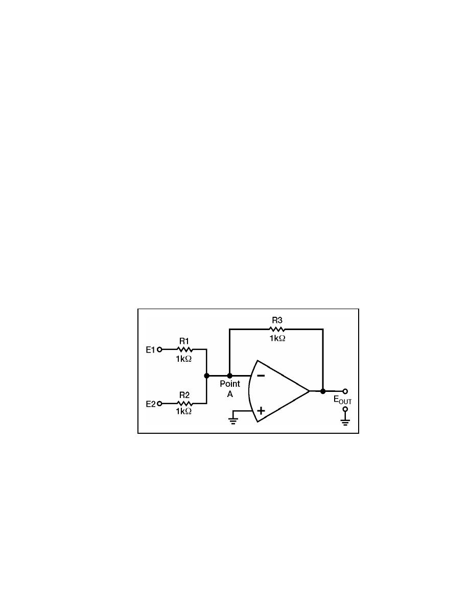
7-82. Figure 7-19 is the schematic of a two-input adder that uses an operational
amplifier. The output level is determined by adding the input signals together (although the
output signal will be of opposite polarity compared to the sum of the input signals).
Figure 7-19. Two-input Adder
7-83. If the signal on input number one (E1) is +3 volts and the signal on input number
two (E2) is +4 volts, the output signal (EOUT) should be -7 volts [(+3 V) + (+4 V) = +7 V
and change the polarity to get -7 V]. With +3 volts at E1 and 0 volts at point A (which is at
virtual ground), the current through R1 must be 3 milliamperes. You can compute this as
follows:
23 June 2005
TC 9-62
7-25


 Previous Page
