_____________________________________________________________________ Special Amplifiers
Therefore, the voltage gain of the inverting configuration of the operational amplifier is
expressed by the following equation:
R2
-
R1
NOTE: As stated earlier, the minus sign indicates that the output signal is 180
degrees out of phase with the input signal.
Noninverting Configuration
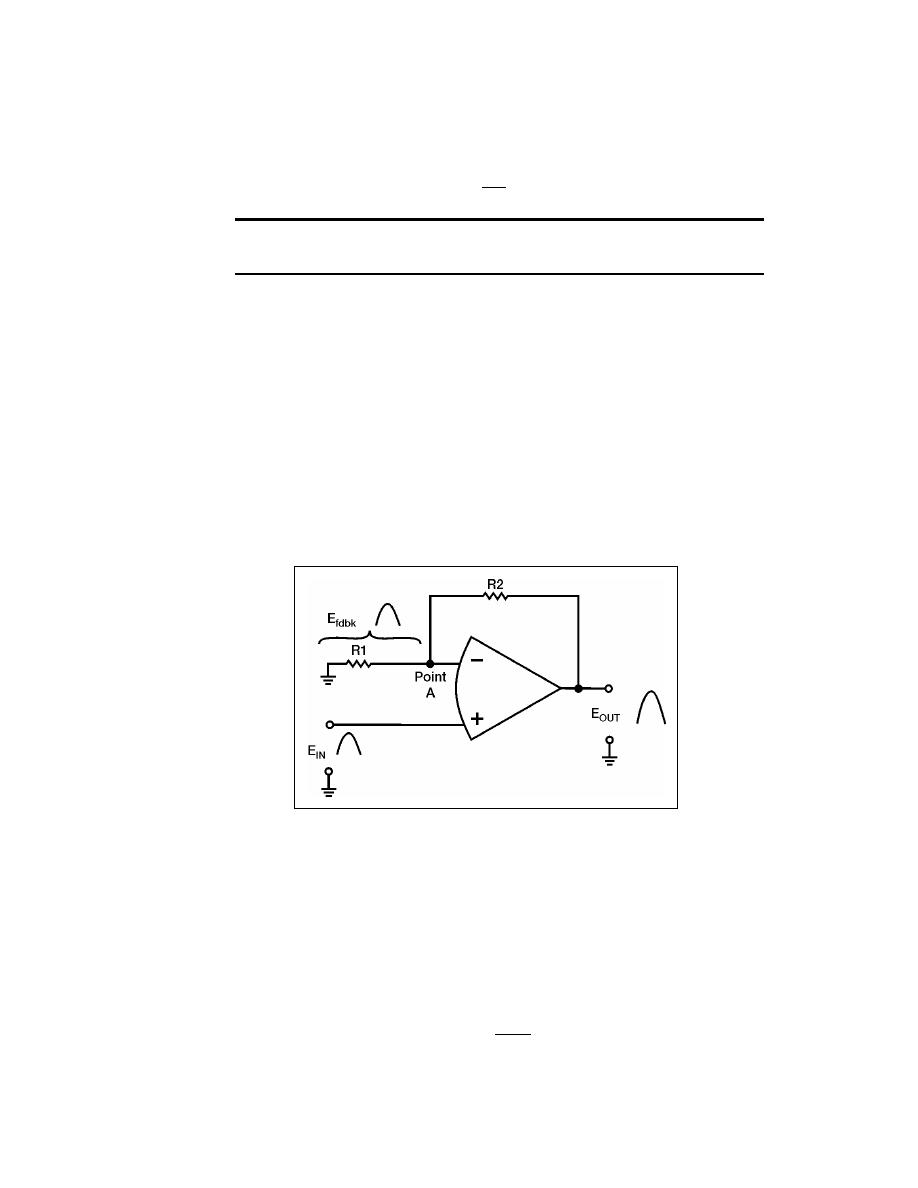
7-68. Figure 7-15 shows a noninverting configuration using an operational amplifier.
The input signal (EIN) is applied directly to the noninverting (+) input of the operational
amplifier. Feedback is provided by coupling part of the output signal (EOUT) back to the
inverting (-) input of the operational amplifier. R1 and R2 act as a voltage divider that
allows only a part of the output signal to be applied as feedback (Efdbk).
7-69. Notice that the input signal, output signal, and feedback signal are all in phase
(only the positive alternation of the signal is shown). It may appear as if the feedback is
regenerative (positive) because the feedback and input signals are in phase. The feedback
is, in reality, degenerative (negative) because the input signal is applied to the noninverting
input and the feedback signal is applied to the inverting input. Remember that the
operational amplifier will react to the difference between the two inputs.
Figure 7-15. Noninverting Configuration
7-70. Just as in the inverting configuration, the feedback signal is equal to the input
signal (for all practical purposes). However, this time the feedback signal is in phase with
the input signal. This is computed as follows:
EIN = Efdbk
Given this condition, you can calculate the gain of the stage in terms of the resistors (R1
and R2). The gain of the stage is defined as follows:
EOUT
Gain =
EIN
23 June 2005
TC 9-62
7-21


 Previous Page
