TC 9-62
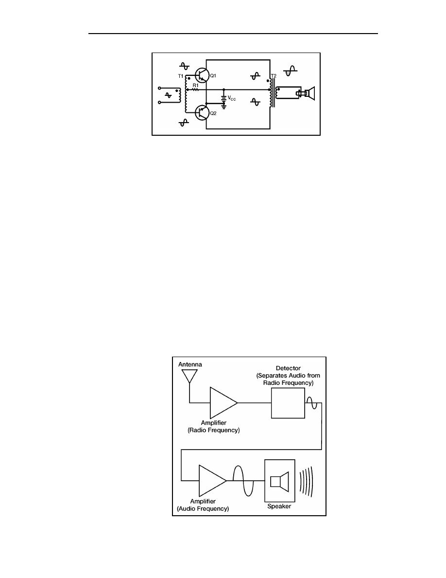
Figure 5-28. Class A Transistor Push-Pull Amplifier
5-91. R1 provides the proper bias for Q1 and Q2. The tapped secondary of T1 develops
the two input signals for the bases of Q1 and Q2. The tapped primary of T2 develops the
output signals of Q1 and Q2. T2 couples the output signal (combined) to the speaker and
provides impedance matching.
5-92. The circuit shown is a class A amplifier. However, because the push-pull amplifier
produces two outputs (from the transistors) 180 out of phase with each other, class B
operation could be used. Half of the original input signal would be amplified by Q1and the
other half by Q2. In this way, the entire output signal would be present at the speaker.
Class B operation is more efficient than class A operation and the gain of the push-pull
amplifier would be more than a single transistor could provide.
SUMMARY
5-93. Now that we have completed this chapter, the following is a short review of the
more important points. Answer the check-on-learning questions, found after the summary,
to determine how much you have learned from this chapter.
AMPLIFIER - a device that enables an input signal to control an output signal.
The output signal will have some (or all) of the characteristics of the input
signal but will generally be larger than the input signal in terms of voltage,
current, or power.
5-26
TC 9-62
23 June 2005


 Previous Page
