TC 9-62
difference between the base and emitter voltages that controls the current flow through the
transistor.
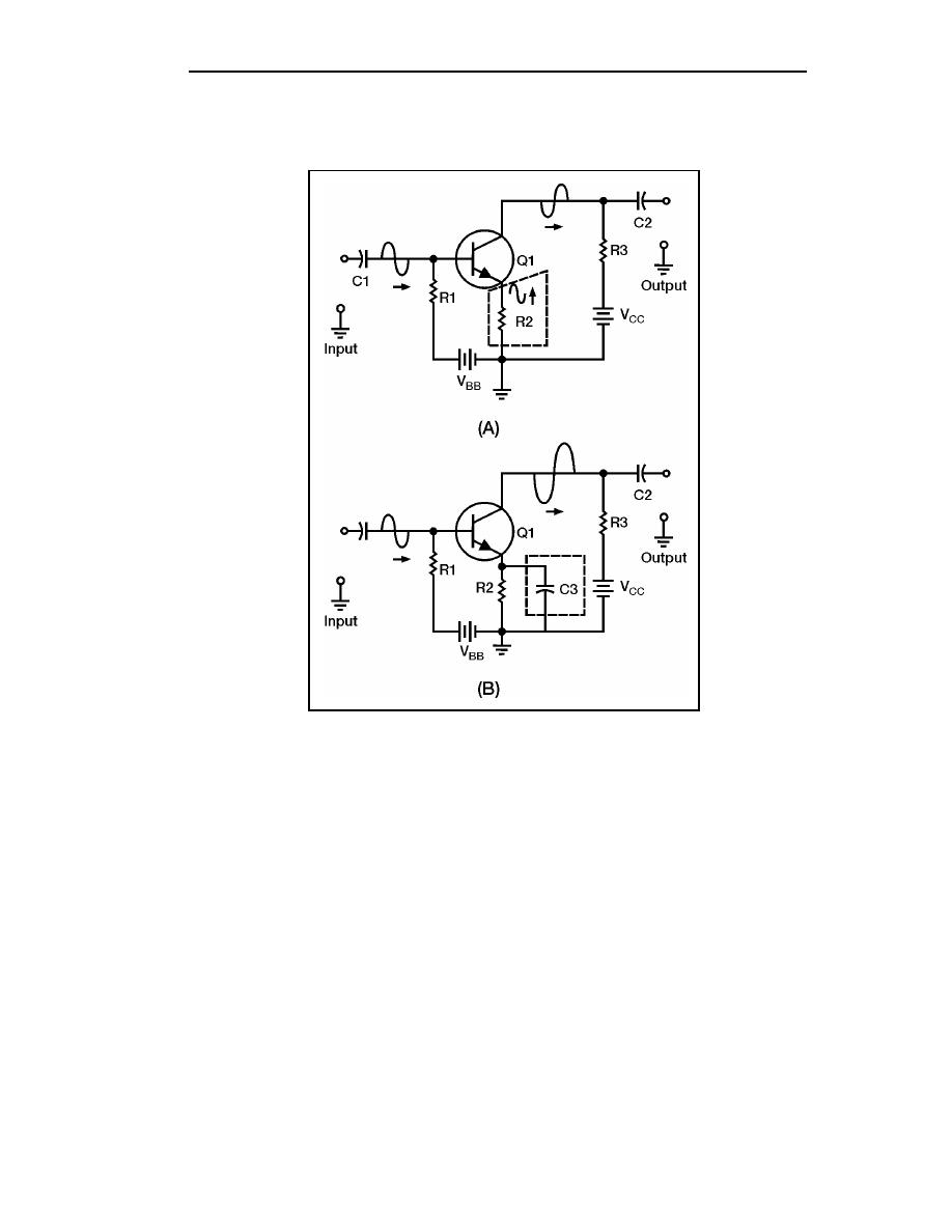
Figure 5-19. Decoupling (Bypass) Capacitor in a Transistor Amplifier
5-74. To stop negative feedback caused by the emitter resistor, you must find some way
to remove the signal from the emitter. If the signal could be coupled to ground (decoupled)
the emitter of the transistor would be unaffected. That is exactly what is done. A
decoupling capacitor (C3 in view B) is placed between the emitter of Q1 and ground
(across the emitter resistor). This capacitor should have a high capacitance so that it will
pass the signal to ground easily. The decoupling capacitor (C3) should have the same
qualities as the coupling capacitors (C1 and C2) of the circuit. Decoupling capacitors are
also called bypass capacitors. Regardless of the method used to provide positive feedback
in a circuit, the purpose is to increase the output signal amplitude.
Negative Feedback
5-75. Negative feedback is accomplished by adding part of the output signal out of phase
with the input signal. You have seen that an emitter resistor in a CE transistor amplifier
will develop a negative feedback signal. Other methods of providing negative feedback are
similar to those methods used to provide positive feedback. The phase relationship of the
feedback signal and the input signal is the only difference.
5-20
TC 9-62
23 June 2005


 Previous Page
