___________________________________________________________________________ Transistors
2-110. There are two basic general classifications of ICs (HYBRID and MONOLITHIC).
In the monolithic IC, all elements (such as resistors, transistors, and so forth) associated
with the circuit are fabricated inseparably within a continuous piece of material (usually
silicon) called the SUBSTRATE. The monolithic IC is made very much like a single
transistor. While one part of the crystal is being doped to form a transistor, other parts of
the crystal are being acted upon to form the associated resistors and capacitors. Therefore,
all the elements of the complete circuit are created in the crystal by the same processes and
in the same time required to make a single transistor. This produces a considerable cost
savings over the same circuit made with discrete components by lowering assembly costs.
2-111. Hybrid ICs are constructed somewhat differently from the monolithic devices. The
PASSIVE components (resistors and capacitors) are deposited onto a substrate
(foundation) made of glass, ceramic, or other insulating material. Then the ACTIVE
components (diodes and transistors) are attached to the substrate and connected to the
passive circuit components on the substrate using very fine (.001 inch) wire. The term
"hybrid" refers to the fact that different processes are used to form the passive and active
components of the device.
2-112. Hybrid circuits are of two general types (thin film and thick film). "Thin" and
"thick" film refers to the relative thickness of the deposited material used to form the
resistors and other passive components. Thick film devices are capable of dissipating more
power but are somewhat more bulky.
2-113. ICs are being used in an ever-increasing variety of applications. Small size and
weight and high reliability make them ideally suited for use in airborne equipment, missile
systems, computers, spacecraft, and portable equipment. They are often easily recognized
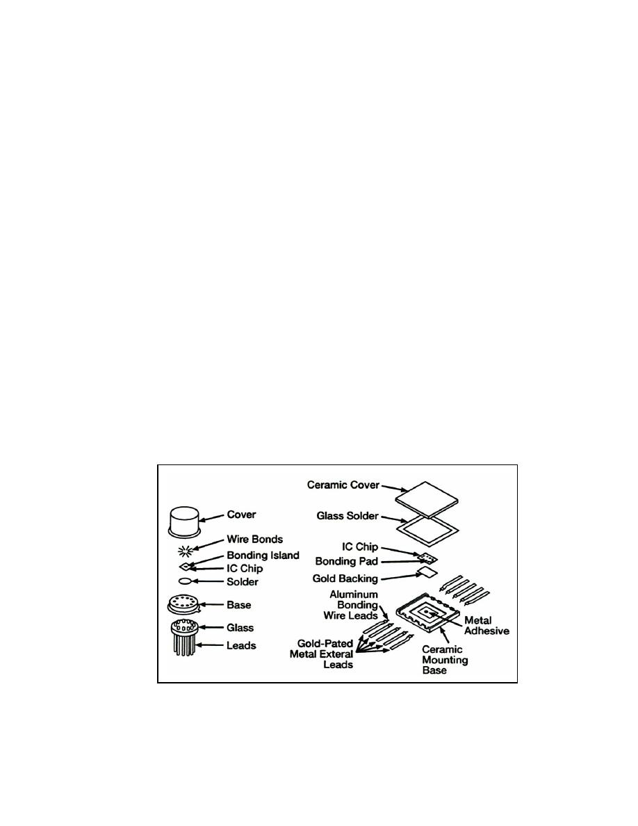
because of the unusual packages that contain the IC. Figure 2-25 shows a typical packaging
sequence. These tiny packages protect and help dissipate heat generated in the device. One
of these packages may contain one or several stages, often having several hundred
components. Figure 2-26 shows some of the most common package styles.
Figure 2-25. Typical IC Packaging Sequence
23 June 2005
TC 9-62
2-35


 Previous Page
