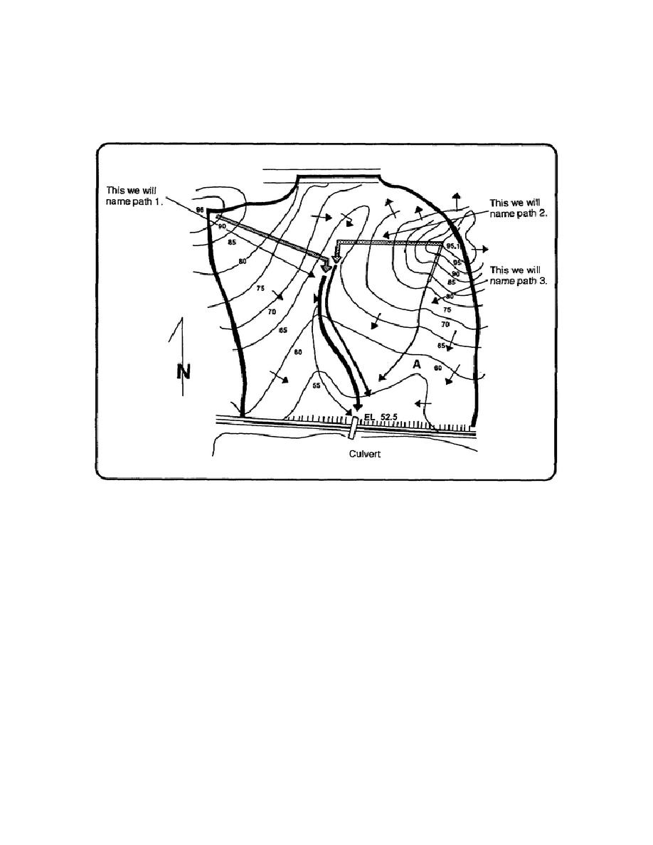
Refer to figure 2-5. Now let's represent the watershed on the western side of the eastern hill. We can represent
the north side of the basin with a flow path from the top of the hill, to the bottom of the swale, and just like path 1,
the water will turn at the bottom of the swale. This we'll name path 2. Path 3 will start at the top of the eastern
hill and move in the hillside swale directly to the culvert. This will represent the southern half of the hillside,
from the south by southwest running ridge to the eastern edge of the watershed.
Figure 2-5. Example basin
STEP 6. Divide flow paths into sheet and ditch (channel) flow. The water that begins to flow down path 1
(figure 2-5) will move slowly, gaining speed as it progresses down the slope. Since the layer depth of the water is
at a minimum, the cover and the vegetation will retard the water's velocity. This is known as a sheet flow
condition, often referred to as overland flow. After the water flows a certain distance, it will converge in the
center and its velocity will increase. Eventually it will gather into a ditch flow condition. Water will move faster
in a ditch flow condition and will take less time to reach the culvert.
Refer to figure 2-5. When the water from path 1 reaches the bottom, it will converge into a ditch at the bottom of
the swale. From the swale to the culvert it will flow in a ditch condition. Since water is flowing at two different
rates, we will separate path 1 into two lengths, path 1A (sheet flow), path 1B (ditch flow).
NOTE: Rule of thumb-water turning in a swale or uphill kinks in the contour lines are good indications of a
transition from sheet to ditch flow.
2-11
EN5465


 Previous Page
