Lesson 3/Learning Event 2
Learning Event 2
MEASURE USING DIAL INDICATORS
The dial indicator can be used for detecting differences in the size of
various parts of a workpiece.
For example, assume we have a 6-inch long
shaft of 3/4-inch diameter which we wish to check for concentricity
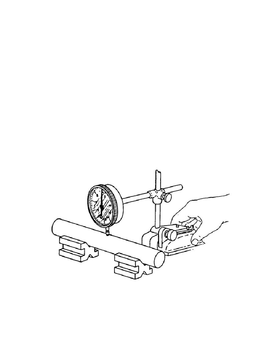
(roundness) and taper. To check or indicate for concentricity, you must use
the setup shown in Figure 43. The V-block clamp screws (not shown) must be
adjusted just enough to permit you to rotate the end of the shaft by hand as
it rests in the blocks.
Loosen the spindle lockscrew of the pedestal, so
you can position the indicator at the proper height. Determine the proper
height by watching the pointer of the indicator. Bring the bottom of the
indicator to bear on the workpiece between the V-blocks until the pointer
moves clockwise .015. At that point, lock the indicator to the spindle of
the pedestal by turning the spindle lockscrew. Now loosen the bezel clamp
and turn the bezel until the 0 on the face of the dial lines up directly
under the pointer of the indicator. After this, clamp the dial in place by
turning the bezel clamp screw.
To check the shaft for concentricity, simply turn the end of the shaft by
hand and note the amount of variation detected by the deflection or movement
of the pointer as the workpiece is revolved.
FIGURE 43.
USING DIAL INDICATOR TO TEST CONCENTRICITY
(ROUNDNESS)
57


 Previous Page
