Lesson 3/Learning Event 2
Since it is obvious that such small movements of the plunger cannot be seen,
the plunger is linked to the indicator hand or pointer through a train of
small gears or through a set of linking levers which multiply any small
movement of the plunger into a larger, sore easily seen movement of the
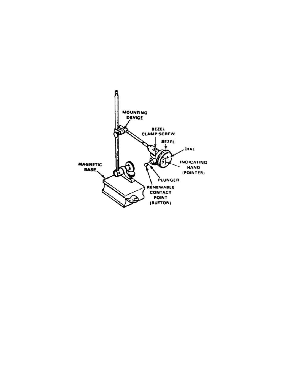
indicator hand. This is why the dial indicator must be mounted rigidly to
some support (magnetic base), Figure 45.
Thus only the plunger can move.
Any movement of the indicator body, in relation to the plunger, would cause
an error in the reading.
FIGURE 45.
DIAL INDICATOR MOUNTED ON A MAGNETIC BASE
When not in use, the plunger spring naturally pushes the plunger outward,
away from the indicator body, to the limit of plunger travel.
On most
standard indicators, the indicator hand comes to rest as shown in Figure 40.
From this position, the hand could only travel to the right, or clockwise.
When you use the indicator properly, the pointer could move either to the
right or left of the 0 (to indicate plus or minus). The indicator must be
set up for use so the plunger has been pushed inward far enough to allow
equal travel to the right or to the left of 0. When using the indicator,
remember that as the plunger moves toward the indicator body, the pointer
moves clockwise, and as it moves away from the indicator body, the pointer
moves counterclockwise.
59


 Previous Page
