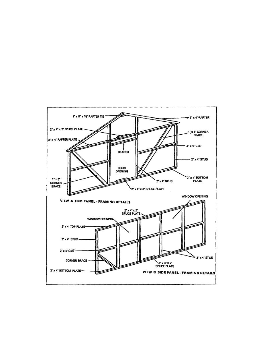
Wall framing for end panels is shown in view A in Figure 117. Wall
framing plans are detail drawings showing the locations of studs,
plates, sills, and bracing. They show one wall at a time. The
height for panels is usually shown. From this height, the length of
wall studs is determined by deducting the thickness of the top or
rafter plate and the bottom plate. Studs placed next to window
openings may be placed either on edge or flat, depending on the type
of windows used. Details for side panels (view B) cover the same
type of information as listed for end panels. The space between
studs is given in the wallframing detail drawing, as well as height
of girt from bottom plate and types of door and window openings, if
any. For window openings the details specify whether the window is
hinged to swing in or out, or whether it is to be a sliding panel.
Figure 1-17.
Typical wall-panel framing details
1-19
EN5155


 Previous Page
